— 2 —
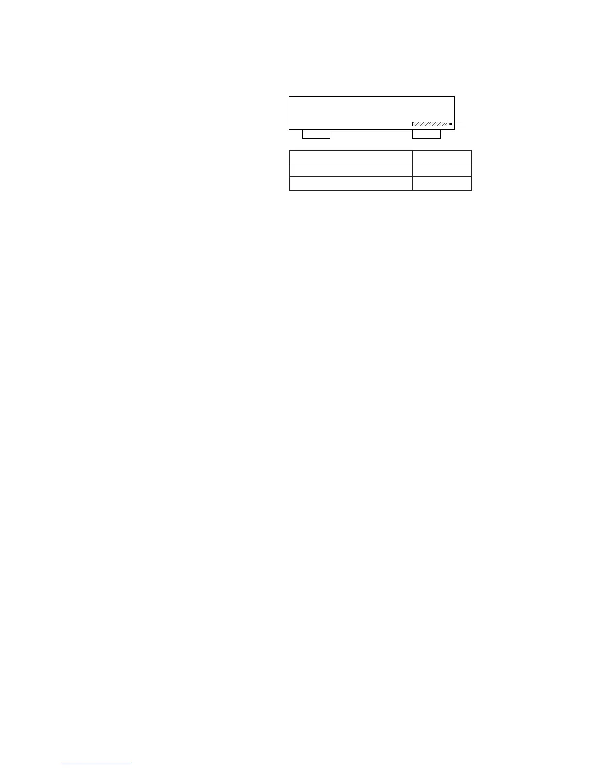
MODEL IDENTIFICATION
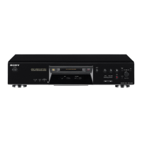
— BACK PANEL —
4-977-679-3π
4-977-679-2π
PARTS No.
US,Canadian model
Other model
TABLE OF CONTENTS
1. SERVICE NOTE ........................................................... 4
2. GENERAL .................................................................... 6
3. TEST MODE
3-1. Setting the Test Mode ......................................................... 11
3-2. Exiting the Test Mode ........................................................ 11
3-3. Basic Operations of the Test Mode .................................... 11
3-4. Selecting the Test Mode ..................................................... 11
3-4-1. Operating the Continuous Playback Mode ..............11
3-4-2. Operating the Continuous Recording Mode ............12
3-4-3. Non-Volatile Memory Mode.................................... 12
3-5. Functions of Other buttons .................................................12
3-6. Test Mode Displays ............................................................ 13
3-7. Meanings of Other Displays ............................................... 13
3-8. Precautions for Use of Test Mode ...................................... 13
4. ELECTRICAL ADJUSTMENTS
4-1. Precautions for Checking Laser Diode Emission ............... 14
4-2. Precautions for Use of optical pickup (KMS-210A) .......... 14
4-3. Precautions for Adjustments............................................... 14
4-4. Creating MO Continuously Recorded Disc........................14
4-5. Temperature Compensation Offset Adjustment ................. 15
4-6. Laser Power Adjustment..................................................... 15
4-7. Traverse Adjustment ...........................................................16
4-8. Focus Bias Adjustment ....................................................... 17
4-9. Error Rate Check ................................................................17
4-9-1. CD Error Rate Check ............................................... 17
4-9-2. MO Error Rate Check ..............................................17
4-10. Focus Bias Check ............................................................... 17
4-11. Adjusting Points and Connecting Points ............................18
5. DIAGRAMS
5-1. Circuit Boards Location ..................................................... 19
5-2. Block Diagrams .................................................................. 20
5-3. Printed Wiring Board — RF Section —............................. 26
5-4. Schematic Diagram — RF Section — ............................... 29
5-5. Schematic Diagram — Digital Section — .........................33
5-6. Printed Wiring Board — Digital Section — ...................... 37
5-7. Printed Wiring Board — Power Section — ....................... 41
5-8. Schematic Diagram — Power Section — .......................... 42
5-9. Schematic Diagram — Panel Section —............................ 45
5-10. Printed Wiring Board — Panel Section —......................... 45
5-11. IC Block Diagrams — Digital Section — .......................... 48
5-12. IC Pin Functions
• IC101 RF Amplifier (CXA1981AR) ............................... 49
• IC121 Digital signal processor, digital servo processor,
EFM/ACIRC encoder/decoder (CXD2535BR)............... 50
• IC201 System Control (M37610MD-067FP) ................. 53
• IC271 Shock-Proof Memory Controller,
ATRAC Encoder/ Decoder (CXD2536R) ....................... 56
• IC301 A/D Converter (CXD8566M) ............................... 58
• IC701 Display control, LED drive ..................................59
6. EXPLODED VIEWS
6-1. Front Panel Section ............................................................ 60
6-2. Chassis Section ................................................................... 61
6-3. Mechanism Deck Section (MDM-2B) ...............................62
6-4. Base Unit Section (MBU-2) ...............................................63
7. ELECTRICAL ADJUSTMENT ................................. 64
Parts No.