2-7
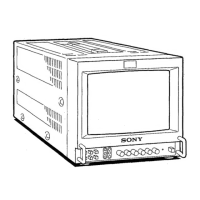
PVM-9L1
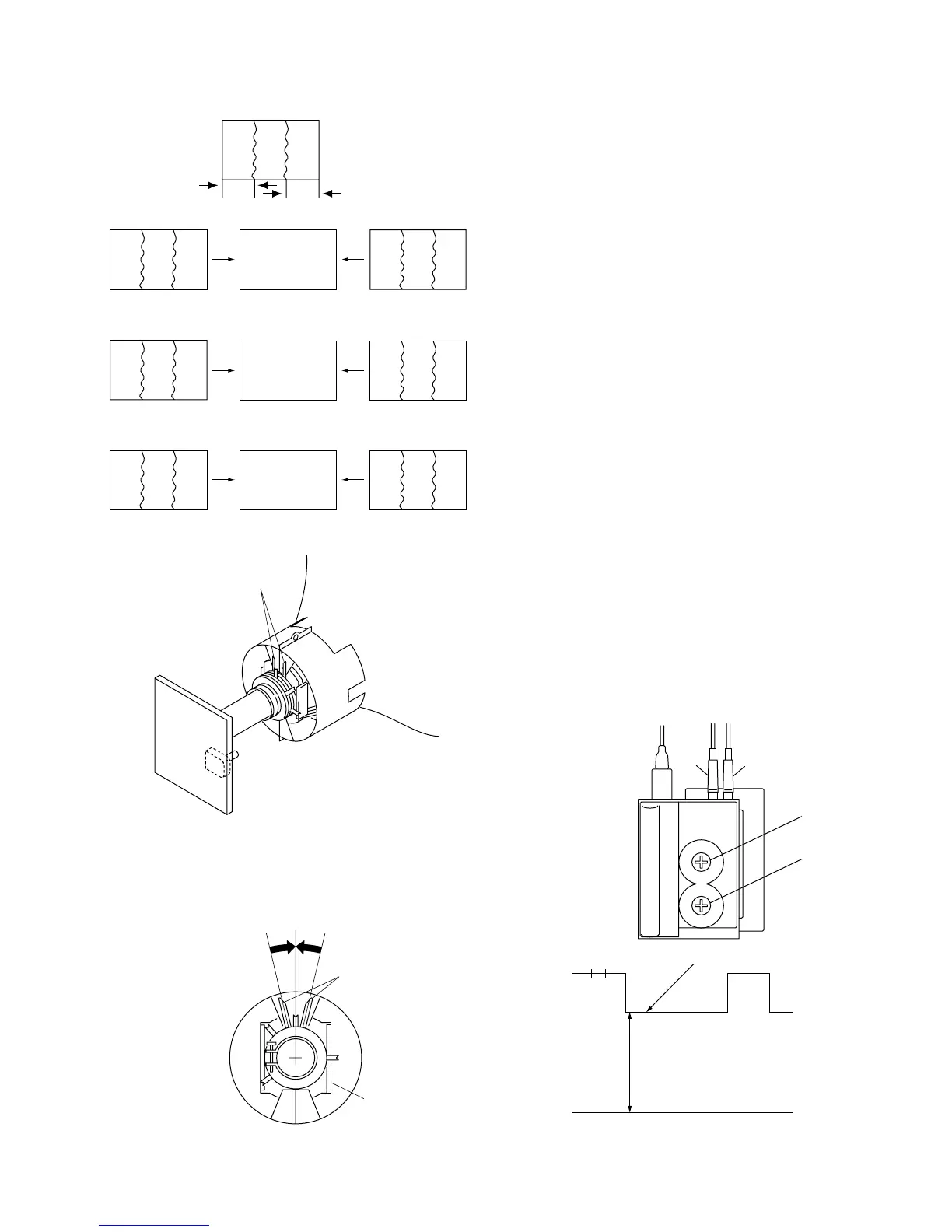
Fig. 2-11
Fig. 2-12
Purity adjustment control
Purity
Purity control
Deflection yoke
2-7. Rough Adjustment for Size
1. Receive PAL SPCB signal.
2. Reduce H size to be able to see whole raster, and set
the brightness to maximam.
3. Adjust raster center with S501.
4. Set brightness to 0.
5. H SIZE 8 17.0 blocks
V SIZE 8 13.0 blocks
Adjust the picture size roughly with V CENT, V SIZE,
H POSITION, H SIZE and PIN AMP.
2-8. G2 Adjustment
Conditions
CONTRAST : 80
BRIGHTNESS : 0
1. Connect the 575/50I all black signal to the LINE A
connector.
2. Select the cathode that shows the highest pedestal level
among the red, green and blue cathodes.
3. Connect an oscilloscope probe to the following test
points and adjust the G2 control (SCREEN) so that the
pedestal level satisfies the specification.
RED : KR
GREEN : KG
BLUE : KB
Standard value A = 95 ±2 VDC
Fig. 2-13
A
Pedestal level
GND
Focus
Focus
Screen
Screen
Fig. 2-1
GGBR
B
R
BRG
RGB
BGR
RBG
GRB
GB
A’
R
A
A’ = A
Fig. 2-2 Fig. 2-3 Fig. 2-4
Fig. 2-5 Fig. 2-6 Fig. 2-7
Fig. 2-8 Fig. 2-9 Fig. 2-10