2-8
PVM-9L1
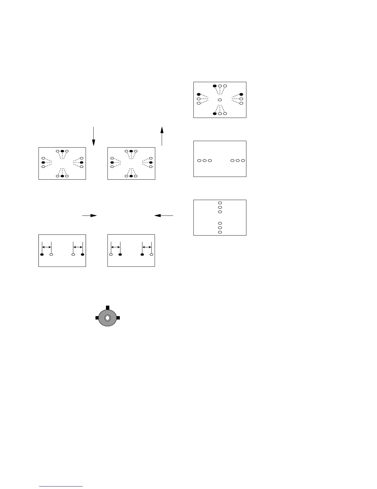
3. The following patterns cannot be corrected by turning
the neck. (Figs.2-19, 2-20, and 2-21)
Fig. 2-19
Fig. 2-20
Fig. 2-21
R G B
R G B
R
G
B
R
G
B
R
B
R
B
G
G
G
(G)
(G)
G(G) (G)
R B
R B
* Gun rotation
The X-axis and Y-axis
beams are distorted on
both sides.
* HCR Large (small)
The horizontal portion of the
G raster is wider (narrower)
than that of the RB raster on
both sides of the screen.
* VCR Large (small)
The vertical portion of the
G raster is wider (narrower)
than that of the RB raster on
both sides of the screen.
2-9. Deflection Yoke Neck Rotation
Adjustment
1. If there are mis-convergence on both sides of X and Y
axes, move the DY neck in the direction of the arrow
so that the degree of mis-convergence satisfies the
allowable range of specification over the entire screen.
2. Insert the wedge between the deflection yoke and CRT
funnel to lock the deflection yoke. (Fig.2-18)
Fig. 2-18
LL
RB BR
LL
BR RB
(1) Reverse cross
mis-convergence pattern
(2) Cross
mis-convergence pattern
Move the deflection yoke
downward.
(3) Pattern of left-sided
deflection yoke
(4) Pattern of right-sided
deflection yoke
Move the deflection
yoke to the right when
viewed from the CRT
screen.
Move the deflection
yoke to the left when
viewed from the CRT
screen.
Move the deflection yoke
upward.
G B R
B
G
R
B
G
R
B G R
R G BB G R
R
G
B
R
G
B
Fig. 2-18 Fig. 2-19
Fig. 2-20 Fig. 2-21