3-2
PVM-9L1
3-2-3. IK Protector Confirmation
1. Supply the power source voltage of 127 to 130 VAC to
the set and turn ON the power.
2. Input the 480/60I all black signal, and adjust the
BRIGHTNESS and CONTRAST knobs on the front
panel to MIN.
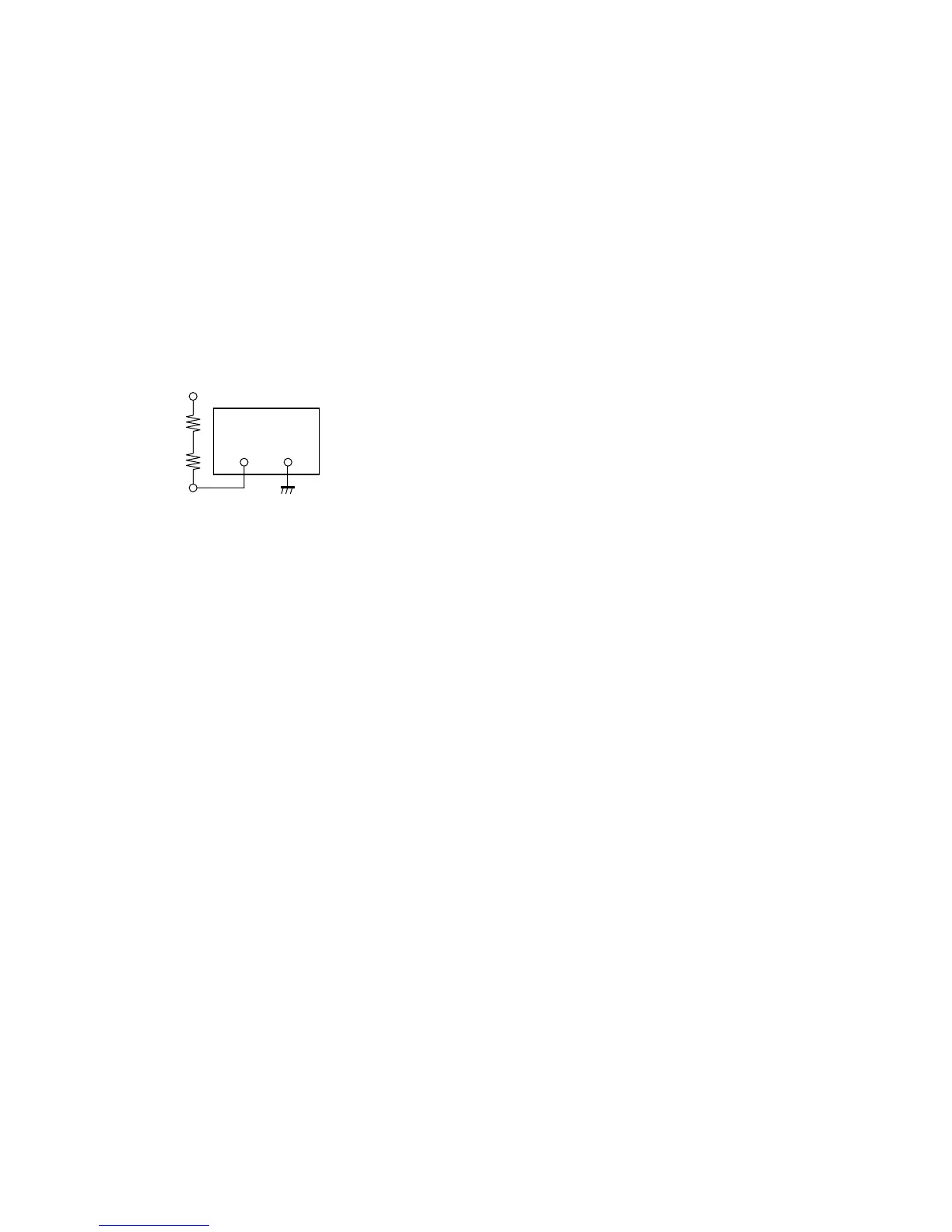
3. Connect the resistor (3 kZ + 47 Z) between the FBT
10 pin (ABL) on the A board and external DC power
supply (-6 V).
Connection diagram
4. Turn ON the DC power supply.
5. Confirm that the protector circuit is activated and
raster disappears.
DC power supply
6 V
3 kZ
47 Z
_+
FBT 10 pin