3-1
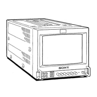
PVM-9L1
Section 3
Safety Related Adjustment
This section explains the adjustment procedure when
safety related component(s) is replaced. Perform the
following adjustment when the safety related component(s)
is replaced.
[Preparation]
Equipment Required
. VG (programmable video signal generator)
VG-854 or equivalent
. DC power supply
. Digital VOM
Advantest TR6845 or equivalent
. Slide induction transformer
n
Start the following adjustments after 5 minutes have
passed after the main power is turned on.
3-1. +B Voltage Check
When the parts shown below are replaced, confirm the
matters described below.
A board
IC601, IC651, R624, R651, R653, T601, PH601
1. Supply the power source voltage of 127 to 130 VAC to
the set and turn ON the power.
2. Input the 480/60I all black signal, and adjust the
BRIGHT and CONTRAST knobs on the front panel to
MIN.
3. Check that the +B voltage is 38.5 to 41.5 VDC.
+B voltage measurement point
Between CN1501 pin-1 on A board and GND.
3-2. Protection Circuit Confirmation
When the parts (with a mark on the circuit diagram)
shown below are replaced, confirm the matters described
below.
A board (HV Protector Circuit)
..... D302, D303, D561, IC301, IC302, Q302, Q303,
Q304, Q559, Q560, Q561, Q562, R316, R317,
R318, R319, R320, R321, R322, R323, R325,
R326, R327, R328, R588, R589, R590, R591,
R592, T501 (FBT)
A board (IK Protector Circuit)
..... D301, D561, IC302, Q301, Q559, Q560, Q561,
Q562, R304, R305, R306, R307, R308, R309,
R310, R311, R312, R313, R314, R315, R588,
R589, R590, R591, R592, T501 (FBT)
3-2-1. Hold-down Circuit Connection
Confirmation
1. Supply the power source voltage of 117 to 120 VAC to
the set and turn ON the power.
2. Input the 480/60I all black signal, and adjust the
BRIGHTNESS and CONTRAST knobs on the front
panel to MIN.
3. Check that the voltage between C314 +side and GND
satisfies the following specified value.
3.8 VDC or more
3-2-2. HV Protector Circuit Confirmation
1. Supply AC power voltage of 127 to 130 VAC to the
unit and turn the POWER ON.
2. Input the 480/60I all black signal, and adjust the
BRIGHTNESS and CONTRAST knobs on the front
panel to MIN.
3. Check that the voltage between the C314 +side and
GND satisfies the specified value.
Specified value : 4.5 to 4.7 VDC
4. Confirm that the protector circuit is not activated.
5. Apply the following voltage between the C314 +side
and GND on the A board, and confirm that the protec-
tor circuit is activated and raster disappears.
4.98 to 5.13 VDC