Features and Functions
10
NSR-25
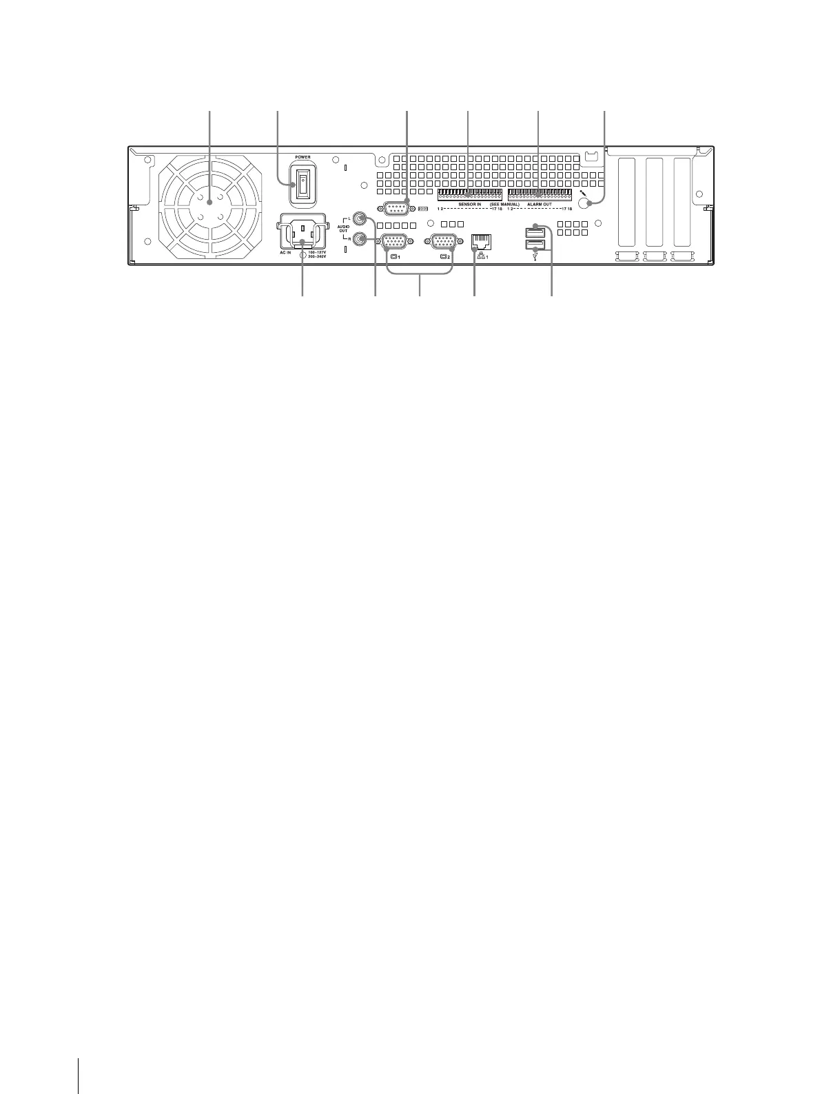
A Fan
Take care not to obstruct the fan grille. If the grille is
obstructed, heat may build up in the unit, leading to
damage and/or fire.
B Power switch
Press the switch in the a position to turn on the unit.
C Serial connector (RS-232C)
Use this connector to connect the control line of the
uninterruptible power supply (UPS).
D Sensor input connector
Use this connector to connect the sensor input lines.
For connection details and wiring diagrams for sensor
inputs, see “I/O Port” (page 27).
E Alarm output connector
Use this connector to connect the alarm output lines.
For connection details and a wiring diagram for alarm
output, see “I/O Port” (page 27).
F Audio input connector*
Use this connector to input audio from a peripheral
audio device, such as a microphone.
G USB connector
Use this connector to connect a USB keyboard, mouse,
USB flash memory or the RM-NS10 remote control to
the NSR.
H LAN connectors
Use these connectors to connect 10 Base-T, 100 Base-
TX, or 1000 Base-T network cables to the NSR.
I Monitor connectors (1 and 2)
Use these connectors to connect a monitor.
J Audio output connectors (L and R)
Use these connectors to output audio to a peripheral
audio device.
K Power supply connector
Use this connector to connect the power cord.
* This feature is not currently supported.
21 43 5 6
a