I/O Port
28
Note
When the wiring diagram 2 is used, the NSR is not
electrically isolated, so be sure to construct external
circuits that will not produce noise, excess voltage, or
overcurrents.
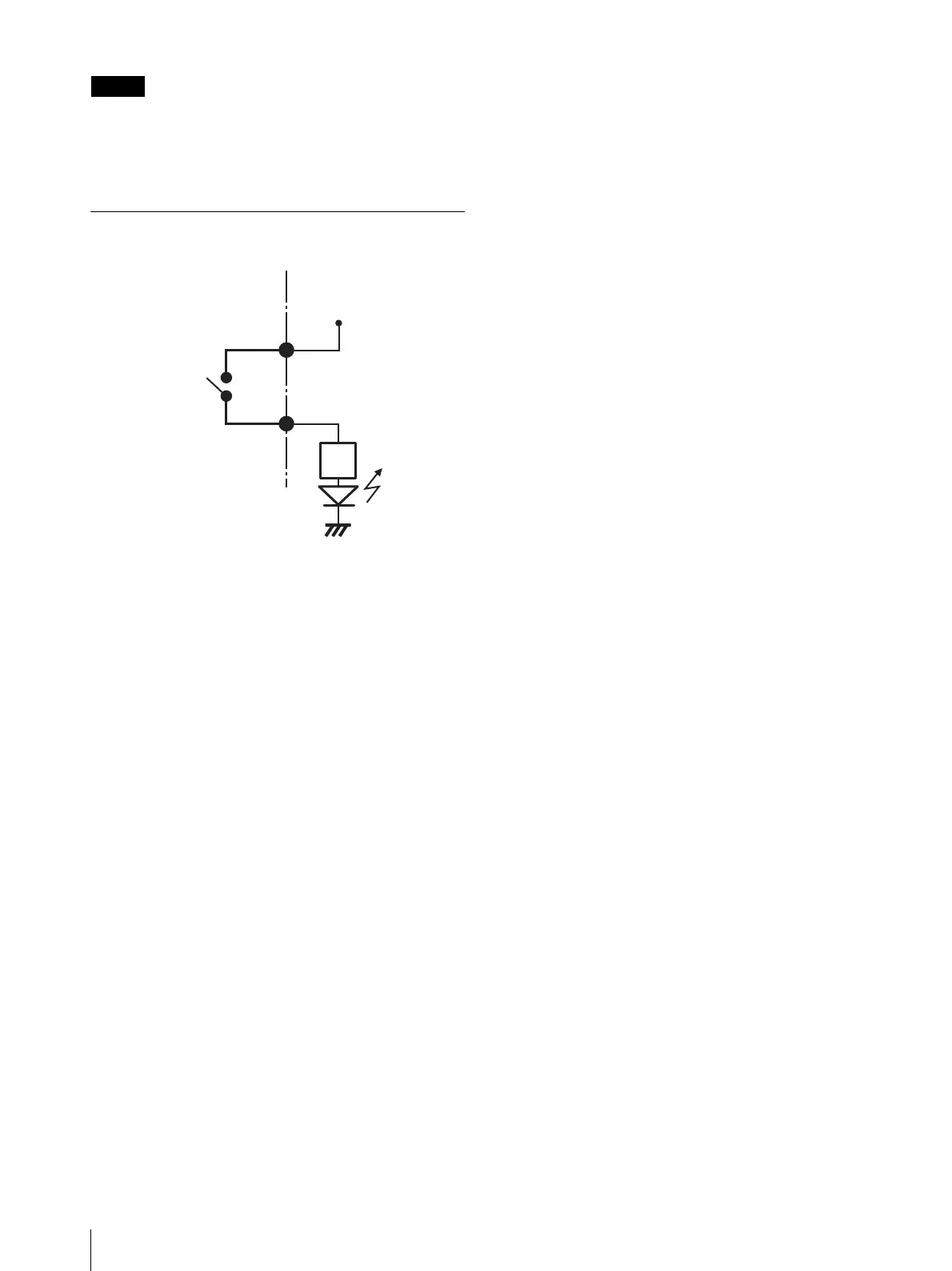
Wiring Diagram for Alarm Output
3, 5, 7, 9, 11, 13,
15, 17pin
(ALARM OUT+)
2, 4, 6, 8, 10, 12,
14, 16pin
(ALARM OUT-)
Magnet relay
24 V AC/24 V DC,
1 A or less
Inside of this unit Outside
5 V
Circuit example
GND