12
HCD-EP50
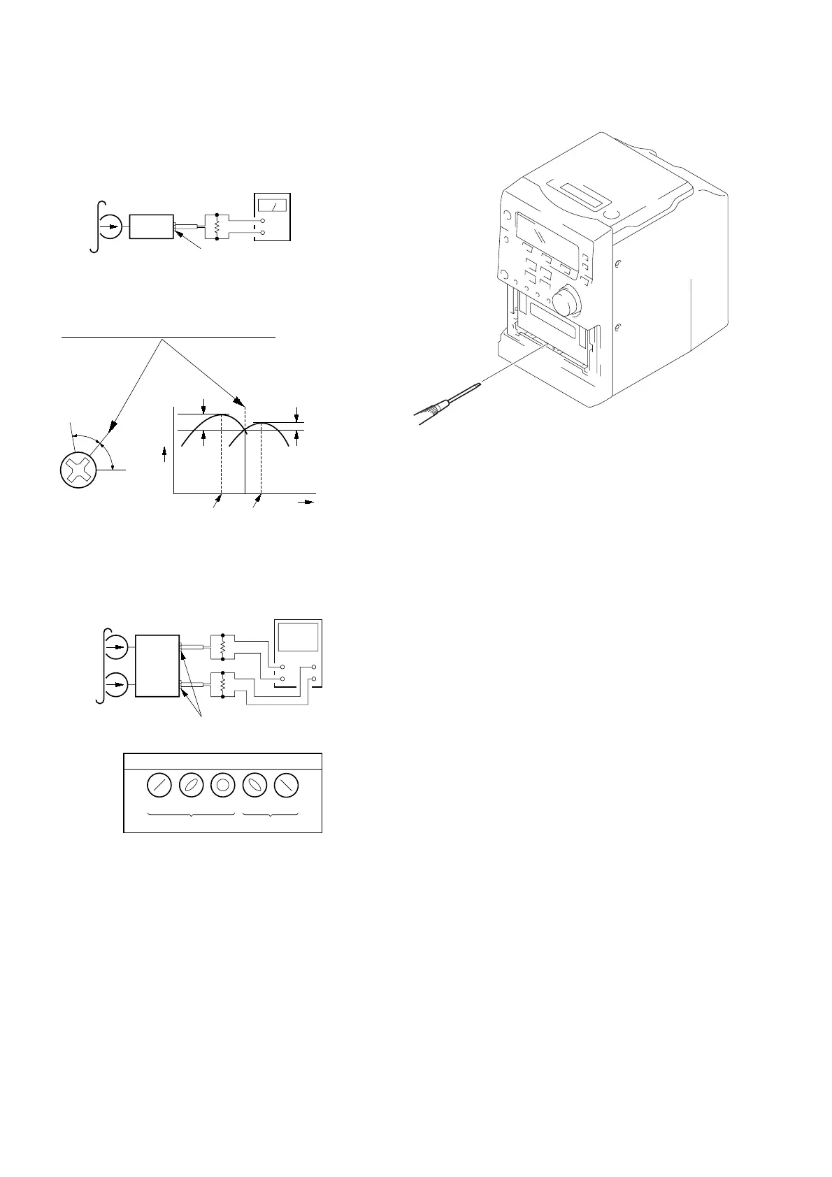
2. Turn the adjustment screw and check output peaks. If the peaks
do not match for L-CH and R-CH, turn the adjustment screw
so that outputs match within 1dB of peak.
3. Mode: Playback (FWD)
4. Repeat step 1 to 3 in playback (REV) mode.
5. After the adjustments, apply suitable locking compound to the
parts adjusted.
Screw
position
L-CH
peak
within
1dB
Output
level
L-CH
peak
R-CH
peak
within
1dB
Screw
position
R-CH
peak
test tape
P-4-A100
(10 kHz, –10 dB)
L-CH
R-CH
MAIN board
SPEAKER terminal (CN17)
oscilloscope
V
H
+
+
–
–
screen pattern
in phase
good wrong
45 °
90 °
135 ° 180 °
47 kΩ
47 kΩ
set
Record/Playback Head Azimuth Adjustment
Procedure:
1. Mode: Playback (FWD)
level meter
test tape
P-4-A100
(10 kHz, –10 dB)
set
MAIN board
SPEAKER terminal (CN17)
47 kΩ
+
–
Adjustment Location: Record/Playback Head.
Note: Refer to “3-7. CASSETTE LID” (see page 10)
 Loading...