31
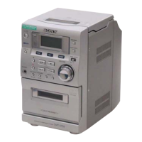
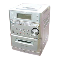
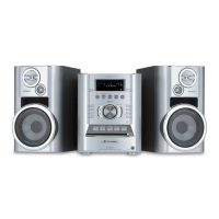
HCD-EP50
6-15. IC PIN FUNCTION DESCRIPTION
• DISPLAY BOARD IC301 µPD78064GF-187-3BA (SYSTEM CONTROLLER, LIQUID CRYSTAL DISPLAY DRIVER)
Pin No. Pin Name I/O Description
1
GENERALDOU
O Serial data output to the FM/AM PLL (U2), LC75392 (U6) and 94HC4094 (U15)
2 GENERALCLK O
Serial data transfer clock signal output to the FM/AM PLL (U2), LC75392 (U6) and 94HC4094
(U15)
3 I2CDATA I/O Two-way data bus with the EEPROM (IC302)
4 STEREO I FM stereo detection signal input from the LA1837 (U1) “L”: stereo
5 I2CCLK O Clock signal output to the EEPROM (IC302)
6IC— Internal connection terminal (connected to ground)
7 X2 O Main system clock output terminal (4.194304 MHz)
8 X1 I Main system clock input terminal (4.194304 MHz)
9
VDD — Power supply terminal
10 XT1 I Sub system clock input terminal (32.768 kHz) Not used (open)
11 XT2 O Sub system clock output terminal (32.768 kHz) Not used (open)
12 RESET I
System reset signal input from the reset signal generator (IC304) “L”: reset
For several hundreds msec. after the power supply rises, “L” is input, then it changes to “H”
13 REMOTE I Remote control signal input from the remote control receiver (X302)
14 PWRFAIL I Power failure detection signal input terminal “L”: power failure, “H”: power on
15 RDSCLK I
Serial data transfer clock signal input from the RDS decoder (IC305)
(Used for the AEP, UK models)
16 CDCLK I Serial data transfer clock signal input from the CD block
17 SENSORB I Tape sensor input terminal Not used (open)
18 SENSORA I Tape play/rec detect sensor input terminal “L” input when the tape play/rec detect
19 CD DOOR SW I
CD lid open/close detect switch (SW300) input terminal “L”: CD lid is closed
20 to 23
CDIN2 to CDIN5
I Not used (open)
24 AMS I
Whether a music is present or not from BA335 (U14) is detected at auto music sensor
“L”: music is not present, “H”: music is present
25 ENCODERA I Jog dial pulse input from the rotary encoder (X303 VOLUME) (A phase input)
26 ENCODERB I Jog dial pulse input from the rotary encoder (X303 VOLUME) (B phase input)
27 AVSS — Ground terminal
28 KEY1 I
Key input terminal (A/D input) SW301 to SW305 (I/1, TUNER, TAPE, CD, PLAY MODE
RDS/DIR) keys input (RDS: used for the AEP, UK models)
29 KEY2 I
Key input terminal (A/D input)
SW306 to SW309 (x, X, Y, TUNER MEM ENTER) keys input
30 KEY3 I Key input terminal (A/D input) SW310 to SW312 (PRESET +/–, DISPLAY) keys input
31 KEY4 I
Key input terminal (A/D input)
SW313 to SW315 (TUNING – . m, TUNING + M >, MUSIC MENU) keys input
32 KEY5 I Key input terminal (A/D input) SW316, SW317 (MEGA BASS, z) keys input
33 ANALYZER I Analyzer level detection signal input terminal (A/D input) Not used (open)
34 TUNED I Tuning detection signal input from the LA1837 (U1) (A/D input) “L”: tuned
35 RDSDATA I Serial data input from the RDS decoder (IC305) (Used for the AEP, UK models)
36
AVDD — Power supply terminal
37
AVREF I Reference voltage input terminal
38, 39
CDOUT1, CDOUT2
O Not used (open)
40 VSS — Ground terminal
41 CDOUT3 O Not used (open)
42 CDDATA I/O Two-way data bus with the CD block
43 CDRESET O Reset signal output to the CD block “L”: reset