28
STR-DA5200ES
SECTION 5
ELECTRICAL ADJUSTMENTS
BIAS ALIGNMENT ADJUSTMENT
Note: Afer 10 minutes or more have passed since the power supply was
turned on, this adjustment is done.
Connection:
Procedure:
1. Connect a digital voltmeter to the CNP1502 (CNP1552,
CNP1602, CNP1702, CNP1752, CNP1802, CNP1852) on the
BIAS board.
2. Press the [POWER] button to turn on the main power.
3. Adjust the RV1501 (RV1551, RV1601, RV1701, RV1751,
RV1801, RV1851) so that the digital voltmeter reading is 5 mV
to 20 mV.
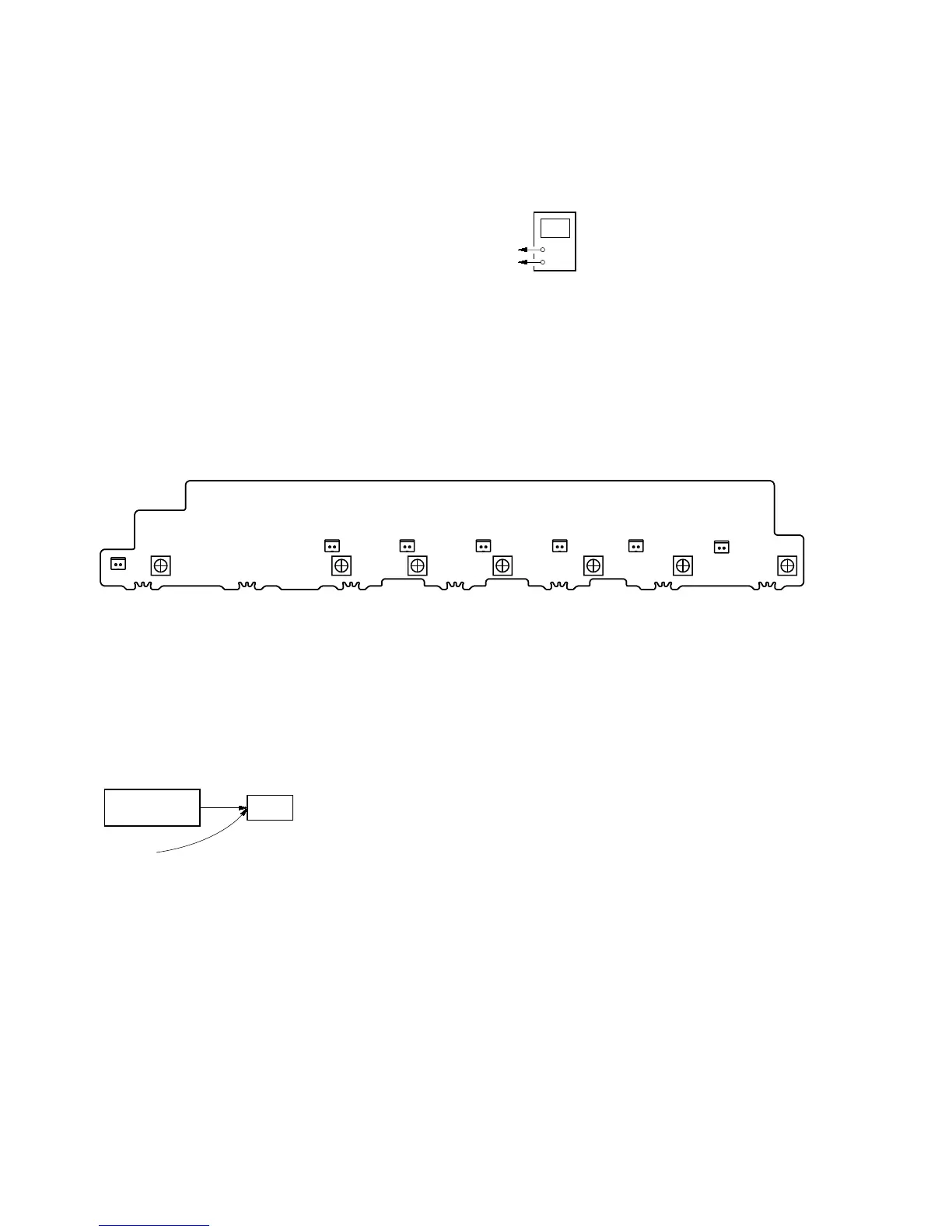
Adjustment and Connection Location:
+
–
digital voltmeter
CNP1502 (CNP1552, CNP1602, CNP1702, CNP1752, CNP1802, CNP1852) pin
1
CNP1502 (CNP1552, CNP1602, CNP1702, CNP1752, CNP1802, CNP1852) pin
2
CNP1752
RV1751
1
2
– BIAS Board (Component Side) –
1
2
1
2
1
2
1
2
1
2
1
2
RV1701
CNP1702
RV1551 RV1501 RV1601
CNP1502CNP1552 CNP1602 CNP1852 CNP1802
RV1851 RV1801
VIDEO CALIBRATION ADJUSTMENT
Adjustment to decide the standard of the video input signal.
Note: After replacing HDMI board, or after “SUPER RESET” of the special
menu mode is executed, perform this adjustment.
Connection:
Procedure:
1. “DVD” is selected by using [INPUT SELECTOR] jog.
2. Connect a color pattern generator to the EXT VIDEO VIDEO
IN jack (J6905) on the S-VIDEO board, DVD S VIDEO IN
jack (J6902) on the S-VIDEO board, COMPONENT VIDEO
DVD IN jack (J6102) on the VIDEO board and DVD VIDEO
IN jack (J6401) on the VIDEO board.
3. Input NTSC color bars signal from the color pattern generator.
4. Press the [POWER] button to turn off the main power
set
color pattern
generator
color bars 100%
S-VIDEO board EXT VIDEO VIDEO IN jack (J6905)
DVD S VIDEO IN jack (J6902)
VIDEO board COMPONENT VIDEO DVD IN jack (J6102
DVD VIDEO IN jack (J6401)
5. While pressing the [TUNING MODE], [MUSIC] and [MULTI CH
IN] buttons, press the [POWER] button to turn on the main
power. It enters the test mode, and display as below.
V.CAL START? N:#, P:@
#: X (NTSC measurement incompletion) or
O (NTSC measurement completion)
@: X (PAL measurement incompletion) or
O (PAL measurement completion)
When “Please Check V.Input” is displayed, Video signal
necessary for the measurement while measuring it last time
was not detected and it became an errorConfirm the input of
the video of the terminal connection etc., and measure the
[MEMORY/ENTER] button again pressing.
6. When the [MEMORY/ENTER] button is pressed, the adjustment
is automatically completed, and result is written in the
EEPROM.
7. Input PAL color bars signal from the color pattern generator.
8. Perform step 4 to 6.

 Loading...