EasyManua.ls Logo

Sony STR-DG910 Service Manual

Sony STR-DG910
106 pages
To Next Page IconTo Next Page
Page #1 background imageLoading...
Page #1 background image
1
SERVICE MANUAL
US Model
Canadian Model
AEP Model
UK Model
E Model
STR-DG910
MULTI CHANNEL AV RECEIVER
AUDIO POWER SPECIFICATIONS
POWER OUTPUT AND TOTAL HARMONIC
DISTORTION:
(Models of area code US only)
With 8 ohm loads, both channels driven, from
20 – 20,000 Hz; rated 100 watts per channel
minimum RMS power, with no more than
0.09 % total harmonic distortion from 250
milliwatts to rated output.
Amplifier section
Models of area code US, CND
1)
Minimum RMS Output Power (8 ohms, 20 Hz –
20 kHz, THD 0.09%)
100 W + 100 W
1)
Stereo Mode Output Power (8 ohms, 1 kHz,
THD 1%)
110 W + 110 W
1)
Surround Mode Output Power
2)
(8 ohms, 1 kHz,
THD 10%)
150 W per channel
1)
Models of area code AEP, UK
1)
Minimum RMS Output Power (8 ohms, 20 Hz –
20 kHz, THD 0.09%)
90 W + 90 W
1)
Stereo Mode Output Power (8 ohms, 1 kHz,
THD 1%)
100 W + 100 W
1)
Surround Mode Output Power
2)
(8 ohms, 1 kHz,
THD 10%)
140 W per channel
1)
SPECIFICATIONS
Ver. 1.0 2007. 04
9-887-656-01
2007D04-1
© 2007. 04
Sony Corporation
Home Audio Division
Published by Sony Techno Create Corporation
This receiver incorporates Dolby* Digital and Pro
Logic Surround and the DTS** Digital Surround
System.
* Manufactured under license from Dolby
Laboratories.
“Dolby”, “Pro Logic”, “Surround EX”, and the
double-D symbol are trademarks of Dolby
Laboratories.
** “DTS” and “DTS-ES | Neo:6” are registered
trademarks of DTS, Inc. “96/24” is a trademark
of DTS, Inc.
This receiver incorporates High-Definition
Multimedia Interface (HDMI
TM
) technology.
HDMI, the HDMI logo and High-Definition
Multimedia Interface are trademarks or registered
trademarks of HDMI Licensing LLC.
XM is a registered trademark of XM Satellite Radio
Inc. (US, CND model only)
This product is manufactured under license from
Neural Audio Corporation.
Sony Corporation hereby grants the used a non-
exclusive, non-transferable, limited license right to
use this product under the US and foreign patents
pending and other related technology owned by
Neural Audio Corporation. (US, CND model only)
“Neural” and “Neural Audio” and “Neural
Surround” are trademarks of Neural Audio
Corporation. (US, CND model only)
– Continued on next page –
Photo: Black type
w
w
w
.
x
i
a
o
y
u
1
6
3
.
c
o
m
Q
Q
3
7
6
3
1
5
1
5
0
9
9
2
8
9
4
2
9
8
T
E
L
1
3
9
4
2
2
9
6
5
1
3
9
9
2
8
9
4
2
9
8
0
5
1
5
1
3
6
7
3
Q
Q
TEL 13942296513 QQ 376315150 892498299
http://www.xiaoyu163.com

Table of Contents

Other manuals for Sony STR-DG910

Question and Answer IconNeed help?

Do you have a question about the Sony STR-DG910 and is the answer not in the manual?

Sony STR-DG910 Specifications

General IconGeneral
Channels7.1
HDMI Inputs3
HDMI Outputs1
Component Video Inputs3
Component Video Outputs1
Digital Audio Inputs (Optical)2
Digital Audio Inputs (Coaxial)1
Total Harmonic Distortion0.09%
Signal-to-Noise Ratio100 dB
Impedance8 ohms
HDMI Version1.3
Audio Formats SupportedDolby Digital, DTS
Video Formats Supported1080p
Audio DecodersDolby Digital, Dolby Digital EX, DTS, DTS-ES, Dolby Pro Logic II, Dolby Pro Logic IIx
Dimensions430 x 350 x 150 mm

Summary

Audio Power Specifications

Power Output and Total Harmonic Distortion

Detailed specifications for power output and total harmonic distortion.

Amplifier Section Specifications

Power output specifications for different area codes (US, CND, AEP, UK).

General Specifications

Specifications for E2 Region Models

Power output specifications specific to the E2 region model.

General Receiver Specifications

Details on power requirements, consumption, dimensions, and mass.

Safety Check-out Procedures

Safety Checks for US Models

Procedures for safety checks and AC leakage testing on US models.

Model Identification and Part Numbers

Identification of different model variations and their corresponding part numbers.

SECTION 1 GENERAL

Getting Started - Front Panel Overview

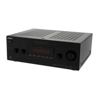
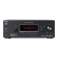
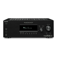
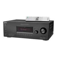
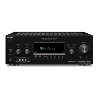
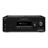
Location and function of front panel controls for US/Canadian models.

Getting Started - Rear Panel Connections

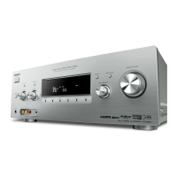
Identification and description of rear panel connections for US/Canadian models.

Getting Started - Remote Commander Overview

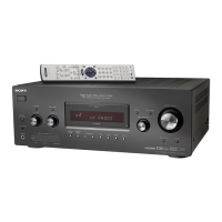
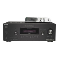
Overview of the remote commander (RM-AAP016) and its basic operation.

Getting Started - Display Indicators

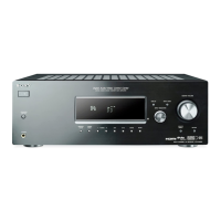
Explanation of indicators on the receiver's front panel for AEP/UK/E2 models.

SECTION 2 DISASSEMBLY

2-1. Case Removal

Procedure for removing the external case of the unit.

2-2. HDMI RE Board Removal

Procedure for removing the HDMI RE board assembly.

2-3. Back Panel Section Removal

Procedure for removing the back panel section.

2-4. Front Panel Section Removal

Procedure for removing the front panel assembly.

2-5. Digital Board Removal

Procedure for removing the digital board.

2-6. Main Board Section Removal

Procedure for removing the main board assembly.

2-7. Standby Board Removal

Procedure for removing the standby board.

SECTION 3 TEST MODE

AM Channel Step Selection Mode

Procedure to select AM tuning step for specific region models.

Vacuum Fluorescent Display Test Mode

Test mode for verifying all segments of the VFD display.

Sound Field Clear Mode

Clears preset sound fields, used before returning unit to client.

Software Version Display Mode

Displays model name, destination, and software version.

Key Check Mode

Tests the functionality of each button on the unit.

Swap All Mode

Swaps audio signals to all channels for speaker testing.

Shipment Mode

Resets all preset contents to the default factory settings.

DCAC Test Mode

Test mode for the DCAC (Digital Auto Calibration) function.

SECTION 4 FM TUNER CHECK

FM Auto Stop Check Procedure

Procedure to check the FM tuner's automatic station stopping function.

SECTION 5 DIAGRAMS

Circuit Boards Location Overview

Visual guide to the location of various circuit boards within the unit.

Block Diagram – Tuner/Audio Section

Block diagram of the tuner and audio processing signal flow.

Block Diagram – Digital Section

Block diagram illustrating the digital signal processing path.

Block Diagram – Video Section

Block diagram of the video signal processing and switching circuits.

Block Diagram – HDMI SW Section

Block diagram of the HDMI signal switching and routing.

Block Diagram – Power Section

Block diagram of the power supply and distribution system.

Printed Wiring Boards – Main Section

Layout of components on the main printed wiring board (Side A).

Schematic Diagram – Main Section (1/4)

Part 1 of the main board schematic diagram.

Printed Wiring Board – Digital Section (1/2)

Layout of components on the digital board (Side A).

Schematic Diagram – Digital Section (1/5)

Part 1 of the digital board schematic diagram.

Schematic Diagram – HDMI RE Section (1/4)

Part 1 of the HDMI RE board schematic diagram.

IC Pin Descriptions - IC1009 ADSP21266SKSTZ-2C

Pin description for IC1009 on the digital board.

IC Pin Descriptions - IC3511 SII9011CLU (HDMI RX)

Pin descriptions for IC3511 on the HDMI RE board.

IC Block Diagrams - IC100 PT6315

Block diagram for IC100 on the display board.

SECTION 6 EXPLODED VIEWS

6-1. Case Section Exploded View

Exploded view of the unit's case and its main external components.

6-2. Front Panel Section Exploded View

Exploded view of the front panel components and their assembly.

6-3. Back Panel Section Exploded View

Exploded view of the back panel components and connections.

6-4. Chassis Section Exploded View

Exploded view of the internal chassis and mounting points.

SECTION 7 ELECTRICAL PARTS LIST

Related product manuals