17
Chapter 1 Overview
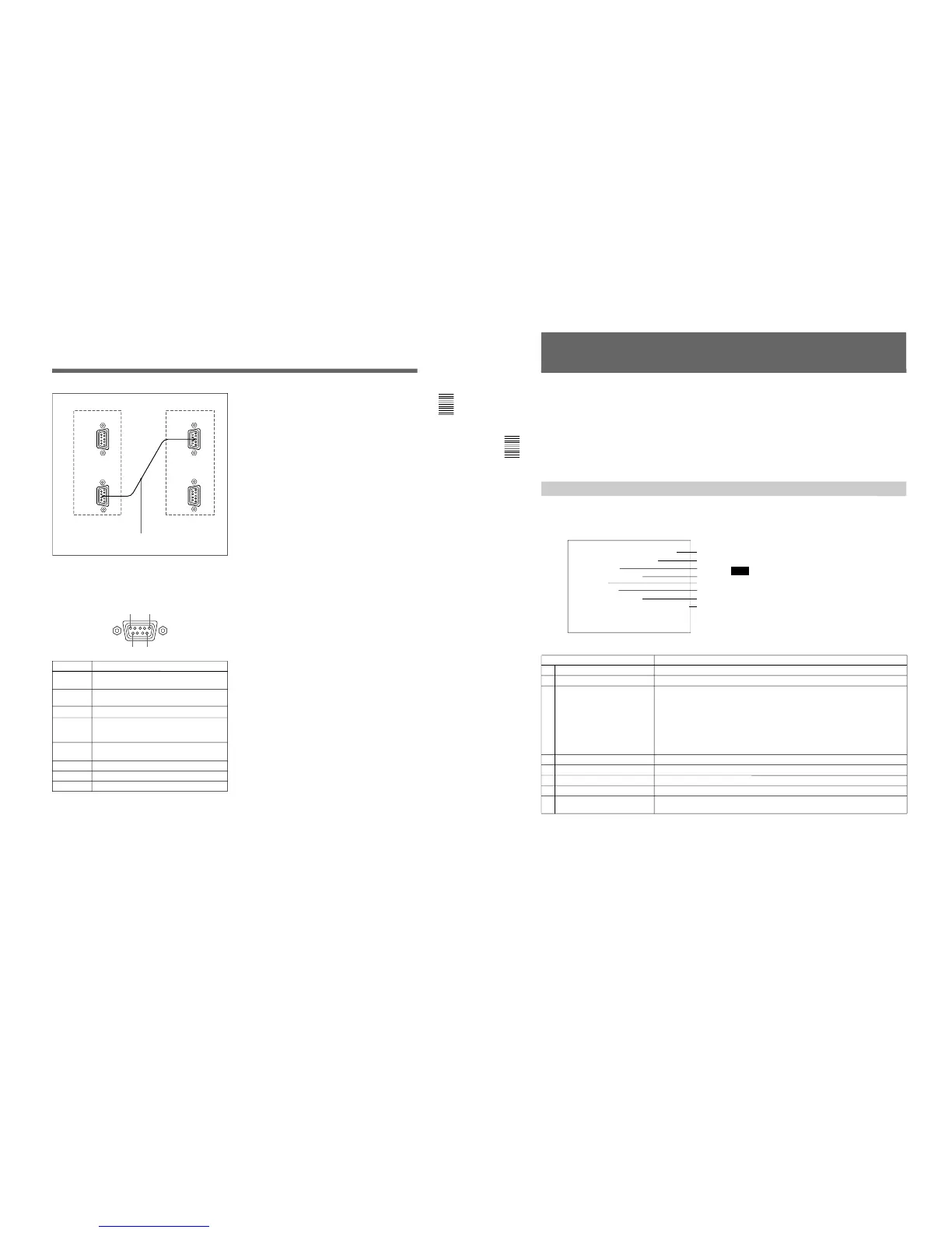
6 REMOTE 2 connector (female, D-sub 9-pin)
Forms a pararell switch and controls the monitor
externally. The pin assignment and factory setting
function assigned to each pin are given below.
Cable with D-sub 9-pin plugs (not supplied)
Monitor 1
Monitor 2
Pin number
1
Set input signal channel 1 (numeric keypad
function)
2 Set input signal channel 2 (numeric keypad
function)
3 Select sync signal (SYNC button function)
4 Set the screen to monochrome, or set for
automatic switching based on the input signal
(MONO MODE button function)
5 Safe area on/off (SAFE AREA button
function)
6, 7 Not connected
8 Tally lamp on/off
9 Ground
Function
1
5
96
All pin function assignments can be changed with the
REMOTE menu.
For information about the REMOTE menu, see “Assigning
the Remote Control Functions (SET UP 2)—REMOTE
Menu” on page 35.
To switch each function between on and off or
between enable and disable, change pin connections in
the following way.
ON or enabled: Short each pin and pin 9 together.
OFF or disabled: Leave each pin open.
7 ISR (Interactive Status Reporting) connector
(female, D-sub 9-pin)
Connect to the ISR system.
8 CONTROL UNIT connector (female, D-sub 9-
pin)
Connects a monitor control unit such as the BKM-10R
using a cable with D-sub 9-pin plugs such as an RCC-
5G (not supplied).
18
Chapter 2 Menu
Menu Structure
The various functions and operating conditions of the
monitor can be set with on-screen menus. Menus
consist of multiple levels of sub menus. The overview
of the menu tree is described in “Menu Directories” on
pages 20 and 21.
Detailed information on the levels of menus is
described at the top of explanation of each menu.
When you select one item on the main menu, the level
1 menu corresponding to the selected item on the main
menu appears.
The adjustments and settings which can be made with
the menus are described below.
Note
On this monitor, menu settings displayed in blue
cannot be changed.
Display of the main menu level
A CONTROL PRESET ADJ menu
B COLOR TEMP ADJ menu
C SET UP menus
D MEMORY CARD menu
E COPY menu
F STATUS menu
G MAINTENANCE menu
H KEY PROTECT
Functions
Sets the preset values for the input signal contrast, brightness, chroma, and phase.
Sets the color temperature.
A menu group for performing monitor setup, consisting of the following.
• INPUT CONFIGURATION menu: Sets the input channel.
• REMOTE menu: Sets the remote control functionality.
• PASSWORD menu: Sets passwords for menus.
• SYSTEM CONFIGURATION menu: Sets power-up conditions and decoder.
• ON SCREEN SET menu: Sets data about the screen display.
• ALIGNMENT menu: Used to adjust the screen convergence and geometry.
• EXTEND menu: Loads the factory default data for the board installed.
Reads and writes setting and adjustment data from/into the memory card.
Operates on data in the memory card.
Copies set-up data from other connected monitors.
Displays the information about the monitor or options installed in the monitor.
Menu for maintenance (typically not used).
When set to ON, function buttons on the control unit (with the exception of menu
operation buttons) will be disable. When set to OFF, key protection is removed.
”A
”B
”C
”D
”E
”F
”G
”H
Displaying the Menus
Press the MENU button.
The menu list is displayed on the screen.