16
Chapter 1 Overview
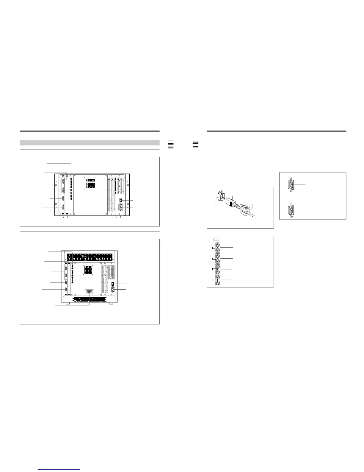
Location and Function of Parts
REMOTE 1 IN connector
REMOTE 1 OUT connector
1 MAIN POWER switch
When turned on, the monitor enters standby mode. By
setting in the SYSTEM CONFIGURATION menu, the
monitor can also be set to enter operation mode when
the MAIN POWER switch is turned on.
For information about the SYSTEM CONFIGURATION
menu, see “Setting Power-Up Conditions and Decoder (SET
UP 4) —SYSTEM CONFIGURATION Menu” on page 39.
2 AC IN connector (3-pin)
Connects the monitor to an AC power source, via the
supplied AC power cord.
3 Analog input/output connectors
RGB signals, component signals (Y/R-Y/B-Y), or
composite sync signals can be fed in the IN
connectors. The type of signal applied to each
connector is set with the INPUT CONFIGURATION
menu. The OUT connectors are used for loop-through
output of the input signal. When not using loop-
through, connect a 75-ohm terminator (not supplied) to
the OUT connectors.
Attach the cord stopper to the AC power cord, and connect it
to the plug holder so that the cord does not come loose.
Cord stopper (supplied)
AC power cord (supplied)
Plug holder
For information about the INPUT CONFIGURATION
menu, see “Setting the Input Configuration (SET UP 1)—
INPUT CONFIGURATION Menu” on page 32.
4 Input option slot
One optional decoder adaptor or input expansion
adaptor can be installed into this option slot.
5 REMOTE 1 connectors (female, D-sub 9-pin)
These are RS-485 serial interface connectors, used for
connecting two or more BVM/HDM-series monitors.
The IN and OUT connectors form a loop-through
connection.
Connect two monitors using a cable with D-sub 9-pin
plugs such as an RCC-5G (not supplied) as shown in
the figure on the next page.
Y/G connectors (BNC)
B-Y/B connectors (BNC)
R-Y/R connectors (BNC)
SYNC connectors (BNC)