5-5
1. Pulse Level Adjustment
Note: The following adjustment menus are under the BK
BOARD menu of the MAINTENANCE menu.
B–Y PULSE LEVEL
R–Y PULSE LEVEL
1. Input the color bar signal.
2. Set the CHROMA data to 1280 using the CHROMA
knob.
3. Connect the oscilloscope to TP504.
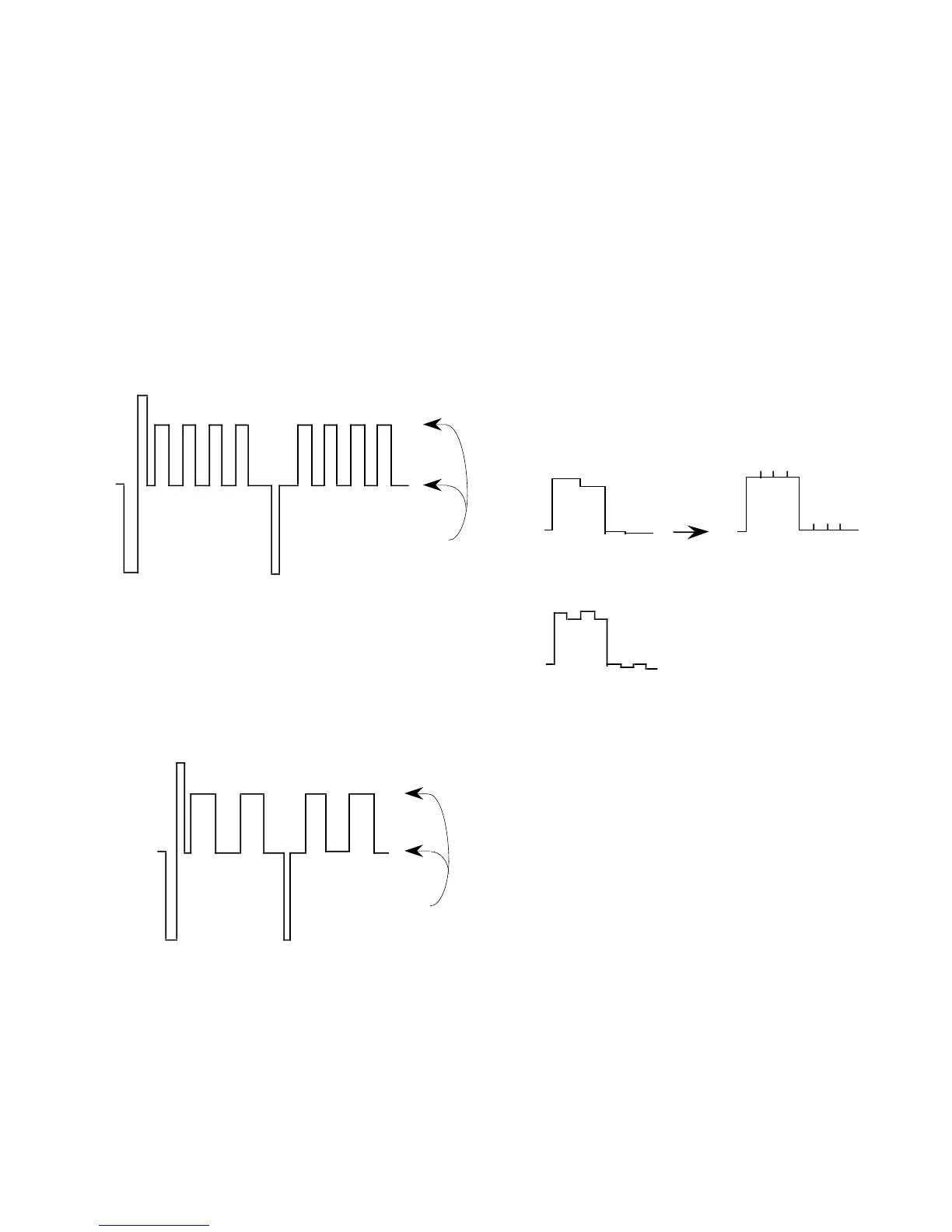
4. As shown in Fig. 5-10, adjust the B–Y PULSE LEVEL
data so that the BLUE waveform becomes flat.
Make flat
Level difference: 0 ±10 mV
Fig. 5-9
5. Connect the oscilloscope to TP104.
6. As shown in Fig. 5-11, adjust the R–Y PULSE LEVEL
data so that the RED waveform becomes flat.
Make flat
Level difference: 0 ±10 mV
Fig. 5-10
2. R–Y Gain, B–Y Gain Adjustment
Note: The following adjustment menus are under the BK
BOARD menu of the MAINTENANCE menu.
B–Y GAIN
R–Y GAIN
Perform this adjustment only for “1. COMPONENT SMPTE/
EBU-N10”.
1. Input the color bar signal.
2. Set the CHROMA data to 1280 using the CHROMA
knob.
3. Connect the oscilloscope to TP304.
4. As shown in Fig. 5-7, adjust the R–Y GAIN data and B–
Y GAIN data so that the GREEN waveform becomes
flat.
R–Y GAIN (+)
R–Y GAIN (+)
Make flat
Level difference: 0 ±10 mV
Fig. 5-11