5-6
3. 0% Setup Adjustment
Note: The following adjustment menus are under the BK
BOARD menu of the MAINTENANCE menu.
R SETUP
G SETUP
B SETUP
1. Input only the Y signal of the color bar signal (Turn off
the R–Y signal and B–Y signal.).
2. Connect the oscilloscope to TP104.
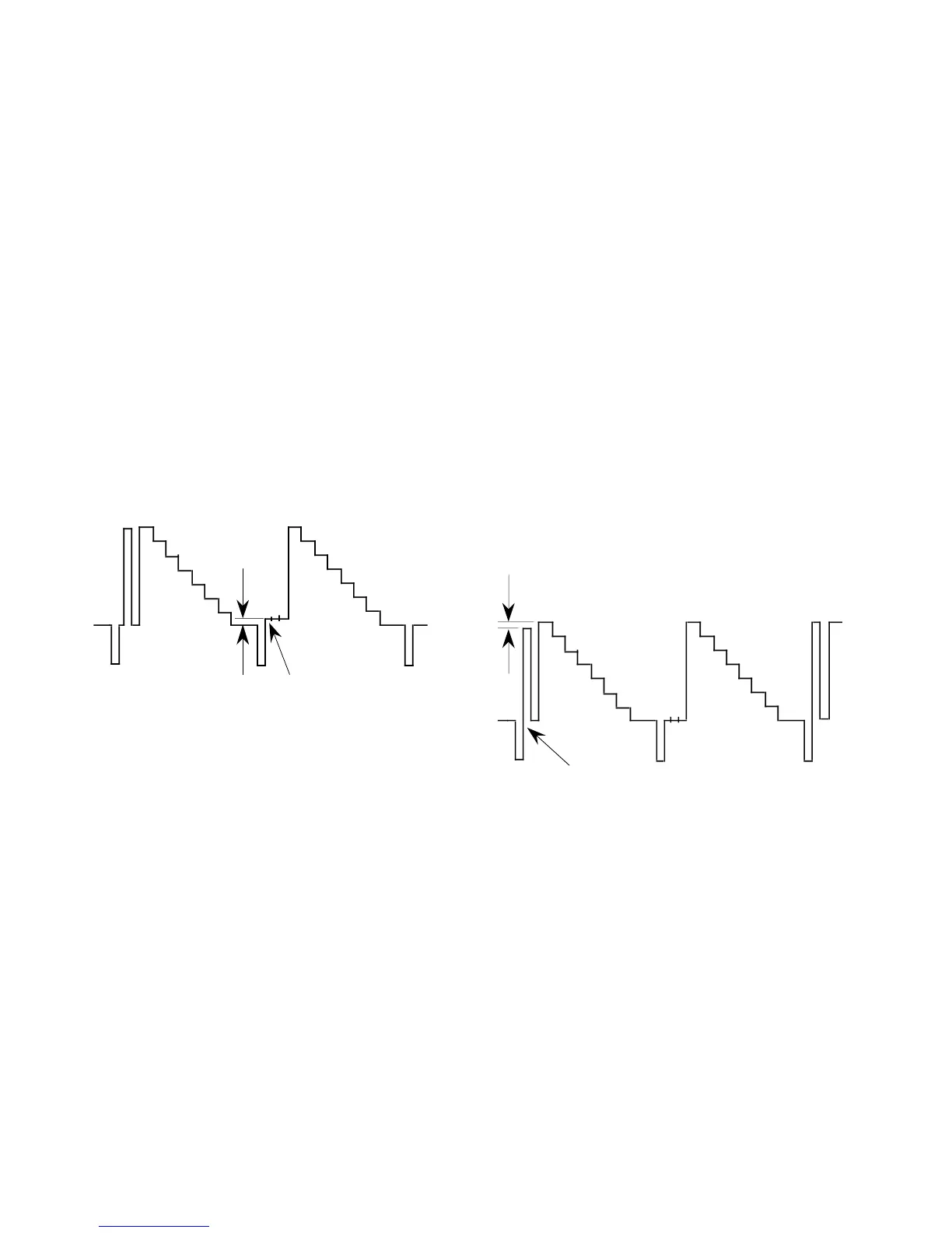
3. As shown in Fig. 5-12, adjust the R SETUP data so that
the black level and setup signal level becomes equal.
4. Connect the oscilloscope to TP304.
5. As shown in Fig. 5-12, adjust the G SETUP data so that
the black level and setup signal level become equal.
6. Connect the oscilloscope to TP504.
7. As shown in Fig. 5-12, adjust the B SETUP data so that
the black level and setup signal level become equal.
4. 100 IRE Adjustment
Note: The following adjustment menus are under the BK
BOARD menu of the MAINTENANCE menu.
R 100 IRE
G 100 IRE
B 100 IRE
1. Input the color bar signal.
2. Connect the oscilloscope to TP104.
3. As shown in Fig. 5-13, adjust the R 100 IRE data so that
the 100 IRE level and 100 IRE pulse level of the signal
become equal.
4. Connect the oscilloscope to TP304.
5. As shown in Fig. 5-13, adjust the G 100 IRE data so that
the 100 IRE level and 100 IRE pulse level of the signal
become equal.
6. Connect the oscilloscope to TP504.
7. As shown in Fig. 5-13, adjust the B 100 IRE data so that
the 100 IRE level and 100 IRE pulse level of the signal
become equal.
Equalize
Black Setup signal
Level difference: 0 ±2 mV
Fig. 5-12
Equalize
Level difference: 0 ±2 mV
100 IRE pulse
100 IRE
Fig. 5-13