PVM-6041QM I
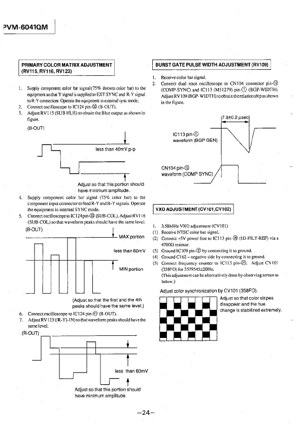
PRIMARY COLOR MATRIX ADJUSTMENT
(RV115, AV116, RV123)
l. Sur.ply comporent color ba-signal(75% chroma color ba-) to the
equipment so that Y signal is supplied to EXT SYNC and R-Y signal
to R-Y connectors Operate !he equipment in external sync mode.
2. Connect oscilloscope to IC\ 24 pin-@ (B-OUD.
3. AdjustRVl 15 (SUB HUE) to obtain the Blue output as shown in
figure.
(B-OUT)
~
less than 40mV p-p
½J-
Adjust so that this portion should
have minimum amplitude.
4. Supply component color bar signal (75% color bar) to 1he
component input connector to feed R-Y and B-Y signals. Operate
the equipment in internal SYNC mode.
5. Connect
oscilloscope to JC 124 pm-® (SUB-COL). Adjust RVI l 6
(SUB-COL) so that waveform peaks should have the same level.
(B-OUT)
-----~~----~MAX portion
less than 60mV
MIN portion
(Adjust so that the first and the 4th
peaks should have the same
level.)
6. Connect oscilloscope to IC 124 pin-@ (R-OUT).
7. AdjustRVl 23 ((R-Y)-IN) so that wavefotn1 peaks should have the
same level.
less than 60mV
t
Adjust so that this portion should
have minimum amplitude.
I BURST GATE PULSE WIDTH ADJUSTMENT (RV109) I
I. Receivecolorbarsignal.
2. Connect dual trace oscilloscope to CN104 connector
pin-@
(COMP-SYNC) and !Cl 13 (MS\279) pin-G) (BOP-WIDTH).
Adjust RV 109 (BGP-WIDTH) to obtain the relationship as shown
in the figure.
IC113 pin-0)
waveform (BGP GEN)
CN104pin-@
waveform (COMP SYNC)
7.8±0.2µsec
I VXOADJUSTMENT(CV101,CV102) I
1. 3.58MHzVXOadjustment(CV101)
( l) Receive NTSC color bar signal.
(2) Connect +5V power line to !CJ13
pin-@ (ID-FILT-REF) via a
47000resistor.
(3) Ground JC109 pin-® by connecting it to ground.
(4) Ground Cl
62- negative side by connecting it to ground.
(5) Connect frequency counter to !Cl 13
pin-@. Adjust CV101
(358FO) for 3579545±20Hz.
(This adjusnnentcan
be alternatively done by observing screen as
below.)
Adjust color synchronization by CV101 {358FO).
m
Adjustsothatcolorstnpes
disappear and the hue
change is stabilized extremely.
-24-