2. 4.43MHz VXO adjustment (CV!02)
(\) Receive PAL colour bar signal.
(2) Connect +12V power line to JC109 pin-@.
(3) Connect frequency counter to IC! 13 pin-®. Adjust CV\02
(443FO) for4433619±20Hz.
(This adjustment can be alternatively done by observing screen as
below.)
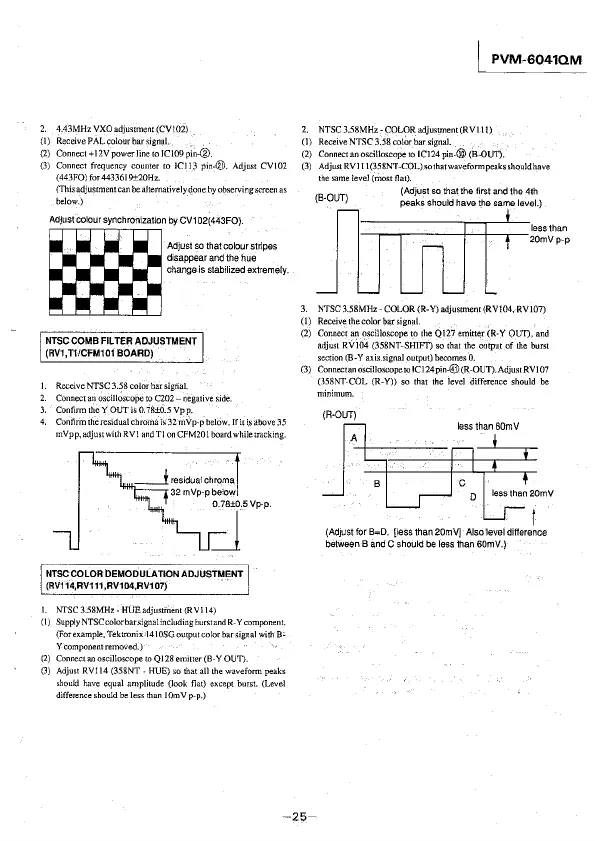
Adjust colour synchronization by CV102(443FO).
change is stabilized extremely.
m
Adjustsothatcolourstripes
disappear and the hue
NTSC COMB FILTER ADJUSTMENT
(RV1,TI/CFM101 BOARD)
I. Receive NTSC 3.~8 color bar signal.
2. Connect an oscilloscope to C202- negative side.
3. Confinn the Y OUT is 0. 78±0.5 Vp p.
4. Confinn the residual chroma is 32 mVp-p below. If it \s above 35
mVp p, adjust with RV 1 and Tl on CFM201 board while tracking.
__j residual chroma
32 mVp-p below
J5V~p
NTSCCOLOA DEMODULATION ADJUSTMENT
(RV114,AV111,AV104,AV107)
- -
I. NTSC 3.58MHz - HUE adjustment (RV 114)
(\) Supply NTSCcolorbarsignal including burst and R-Y component.
(For example, Tektronix 14\0SG output color bar signal with
B:
Y component removed.)
(2) Connect an oscilloscope to
Q 128 emitter (B-Y OUT).
(3) Adjust RVI 14 (358NT
- HUE) so that all the waveform peaks
~hould have equal amplitude (look flat) except burst. (Leve!
difference should be
less than IOmV p-p.)
I PVM-6041QM
2. NTSC 3.58MHz - COLOR adjustment (RV! 11)
(1) Receive NTSC 3.58 color bar signal.
(2) Connect an osci!loscope to IC124 pin.@ (B-Ol/1).
(3) Adju~t RV] I 1(358NT-COL)sothatwaveformpeaksshouldhave
thesame!evel(mostflat).
(B-OUT) (Adjust so that the first and the 4th
n=i ITTTr:-2
1
~0:.v,
h
·"
J lJ m P·P
3. NTSC 3.58MHz - COLOR (R-Y) adjustment (RV104, RVl07)
(I) Receivethecolorbarsignal.
(2) Connect an oscilloscope to the Q\27 emitter (R-Y OUT), and
adjust RV104 (358NT-SHJFT) so that the output of the burst
section (B-Y axis.signal output) becomes 0.
(3) ConnectanoscilloscopetolCl24pin-@(R-OUT).AdjustRV107
(358NT-COL (R-Y)) so that the level difference should be
minimum.
(A-OUT)
A
less than 60mV
(Adjust for B=D. [less than 20mV] Also level difference
between B
;ind C should be less than 60mV.)
-25-