Installation Sorensen DCS Series 3kW Supplies
Contact Installation
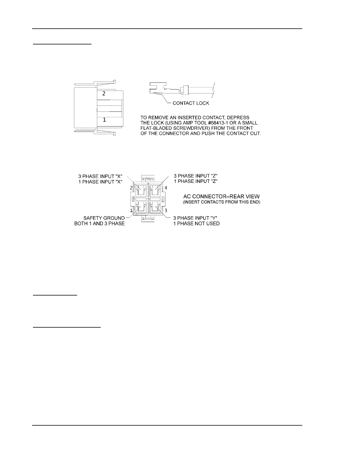
5. Insert contact with attached wire into the connector until lock snaps into place. See
Figure 2-3 and Figure 2-4 to complete the connector for either single or three phase
input.
Figure 2-3 Contact Orientation
Figure 2-4 AC Wire Locations
2.5.3 Strain Relief Assembly
The strain relief is assembled from supplied pieces and attaches to the AC input connector to
provide support for the AC input cord.
Parts Supplied
•
Two (2) pieces strain relief (Part number MI-6432-661)
•
Two (2) screws (Part number MS-6P12-10)
Assembly Instructions
1. Snap off the rectangular bushing attached to each piece of the strain relief.
See Figure 2-5.
2. Install bushings on strain relief pieces, if required:
If cable diameter is within 0.1" to 0.4", install bushings.
If cable diameter is within 0.5" to 0.74", do not use bushings.
2-6 Operation Manual
 Loading...