Advanced Operation Sorensen DCS Series 3kW Supplies
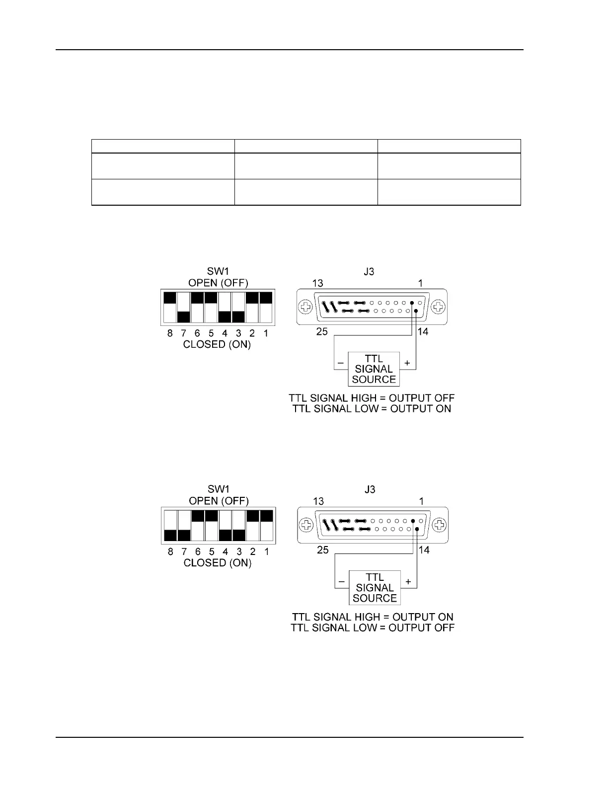
2. Connect the TTL signal source to pin 14 (TTL Shutdown Input/positive) and pin 2
(Return for Shutdown Input) on the J3 connector on the rear panel. See Figure 4-14 and
Figure 4-15.
3. Set internal switch SW1-8 to select the desired circuit logic as defined in the table below.
Switch SW1-8 Setting TTL Signal Level Output Condition
OPEN (Positive logic) HIGH OFF
LOW ON
CLOSED (Negative logic) HIGH ON
LOW OFF
The red S/D (Shutdown) LED on the front panel lights up when the Shutdown circuit is
activated.
Figure 4-14 Using Shutdown with a TTL Compatible (Positive Logic)
Figure 4-15 Using Shutdown with a TTL Compatible (Negative Logic)
4-16 Operation Manual
 Loading...