Sorensen DCS Series 3kW Supplies Installation
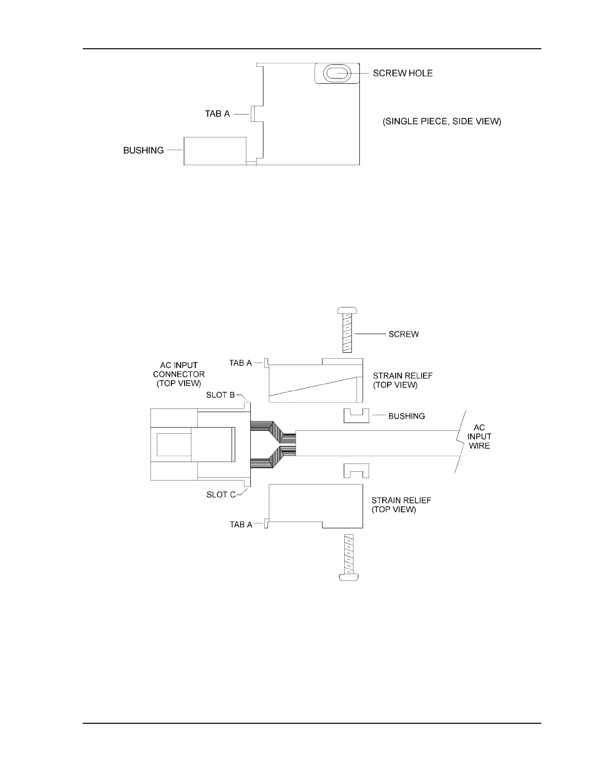
Figure 2-5 Strain Relief, as Supplied
3. Insert strain relief tab A into AC input connector slot B. Insert second strain relief tab A
into AC input connector slot C. See Figure 2-6.
4. Install screws in holes provided on outside of strain relief pieces. Thread through to
screw standoff inside opposite piece. Tighten to clamp outer jacket of AC wire securely,
ensuring that the side of the strain relief slips into the corresponding rabbet on the
opposite piece.
Figure 2-6 Strain Relief Assembly
Operation Manual 2-7



 To Next Page