Advanced Operation Sorensen DCS Series 3kW Supplies
WARNING
Exercise caution when resetting internal jumpers. Review Section 2.2 Safety and
follow procedures for removing the cover and resetting jumpers in Section 4.2.3.
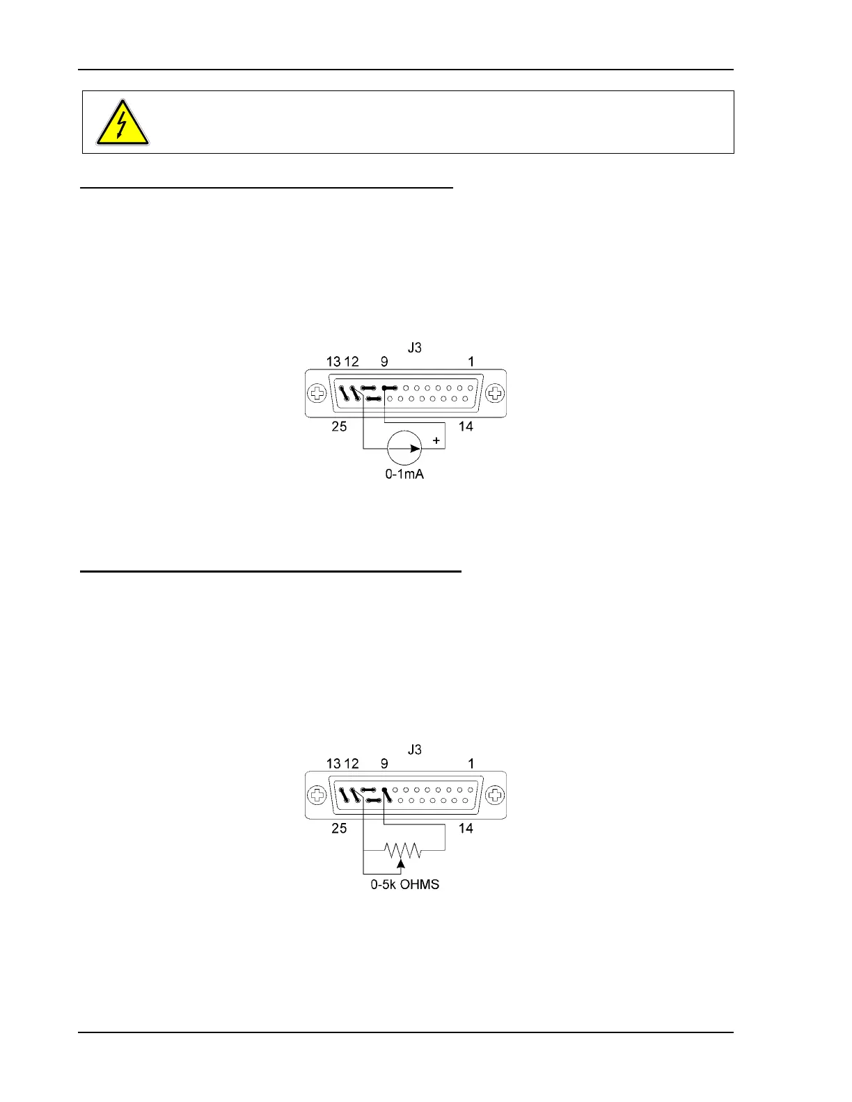
Programming Output Voltage with a 0-1 mA Source
1. Remove the jumper between pins 20 and 21 of connector J3.
2. Connect the external programming source between pin 9 (voltage programming
input/positive) and pin 12 (return) of connector J3.
Varying the current source from 0 to 1 mA will vary the output voltage from 0 to 100% of the
model rating. Adjusting the front panel current limit control sets the output current limit.
Figure 4-6 Programming Output Voltage with a 0-1 mA Source
Programming Output Voltage with a 0-5k Resistance
1. Remove the jumpers connecting pins 8 to 9 and pins 20 to 21 on connector J3.
2. Connect pins 9 (voltage programming input/positive) and 21 (1 mA current source for
voltage control) to the counter-clockwise end of the 5k potentiometer and connect the
tap and clockwise end of the potentiometer to pin 12 (return).
Adjusting the resistance from 0 to 5k will vary the output voltage from 0 to 100% of the model
rating. The output current limit is set locally by adjusting the front panel current limit control.
Figure 4-7 Programming Output Voltage with a 5k ohm Resistance
4-10 Operation Manual
 Loading...