91369 Service Manual 3-19
Theory
The Remote Interface system handles Ethernet connections to remote monitors and modules.
It also:
• Broadcasts the existence and configuration of network devices to each other.
• Allows remote parameter attaches and remote key press connections across the network.
• Downloads the module table code to remote monitors to create the same user interface on multiple
monitors.
• Supports the Alarm Watch and Remote View functions.
• Handles multicast waveform data.
The Recorder subsystem controls local and network printers.
The Alarm subsystem handles the standard alarms. Modules send alarm conditions over SDLC and, in
response, the alarm subsystem sends alarm messages to the tone, display, record, and network tasks. It
receives messages from the network for Alarm Watch alarms and from SDLC tasks for module/channel adds
or deletes.
Display
The internal display is a 640 × 480, active matrix, thin-film-transistor (TFT) color Liquid Crystal Display (LCD).
It receives 18 data signals, 4 timing signals, +5 V and ground. Backlight voltage is produced via an attached
1000 VAC inverter.
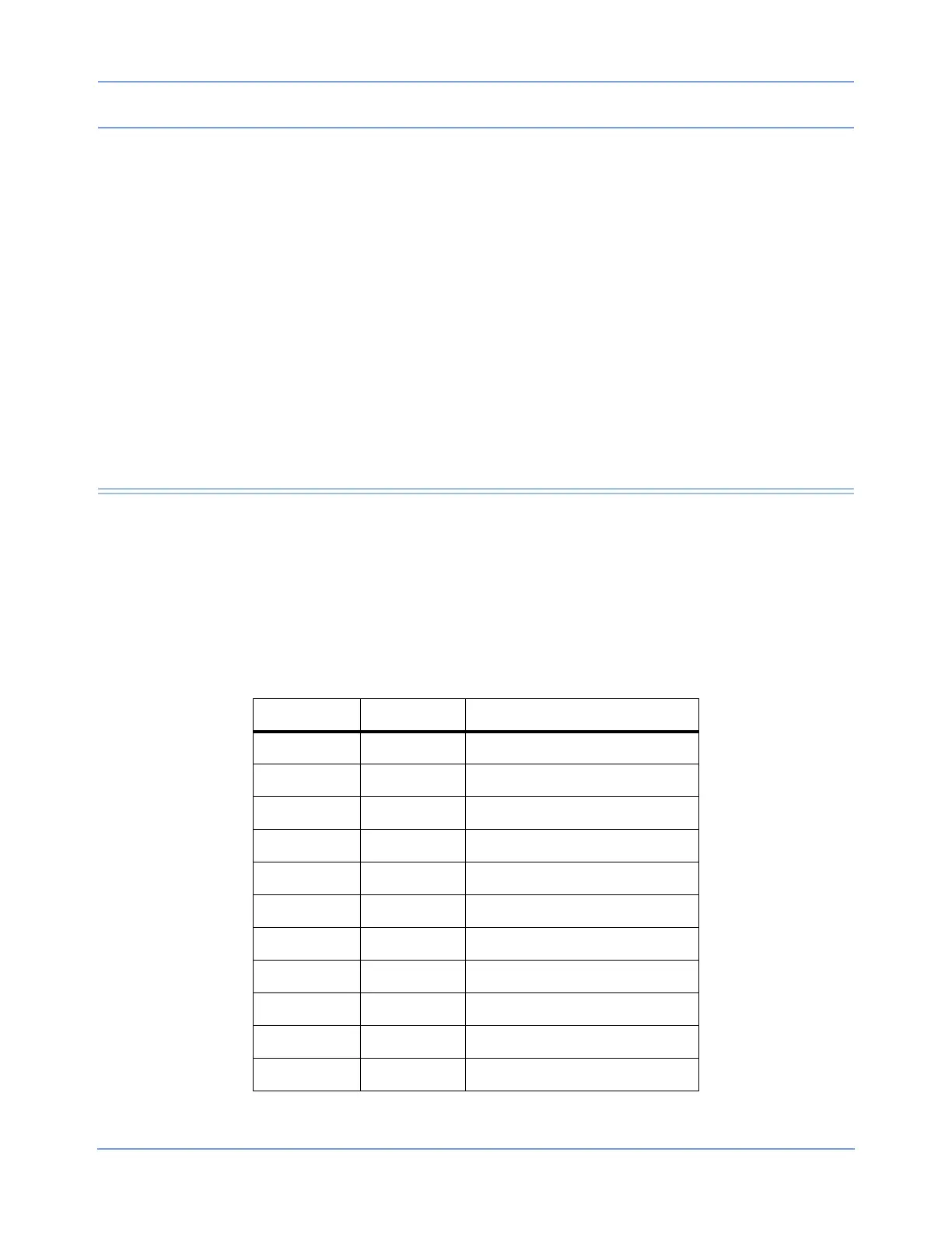
The pinout of the display connector (at the display) is provided in Table 2. The backlight is connected via a
separate 3-pin connector
Table 2: Display Connector Pinouts on CPU PCBA P161
Pin Number Symbol Description
1GND
2CLK
3 HSYNC Horizontal Sync
4 VSYNC Vertical Sync
5GND
6R0Red Data LSB
7R1
8R2
9R3
10 R4
11 R5 Red Data MSB