Theory
91369 Service Manual 3-22
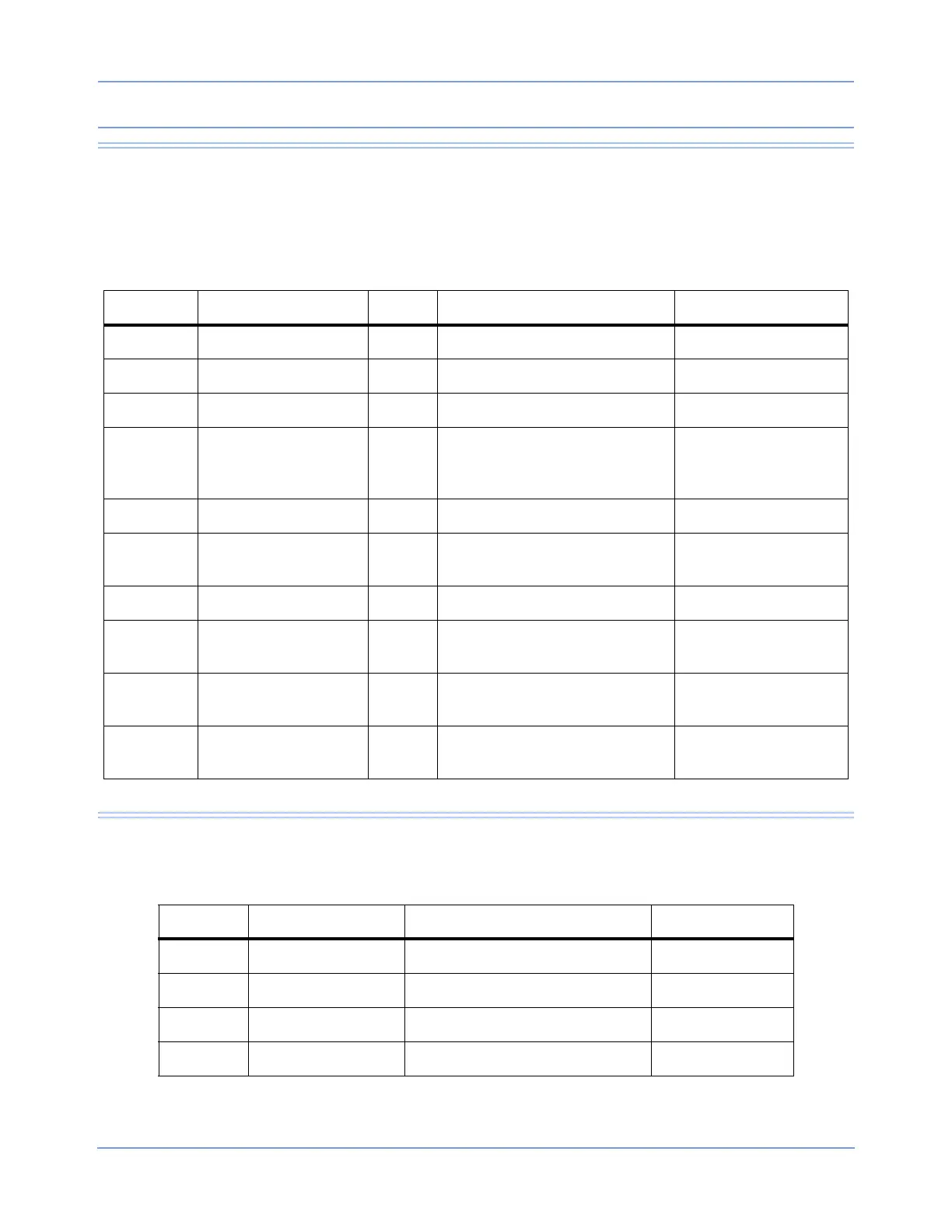
CPU PCBA Jumpers
The CPU PCBA also has several jumpers for various configuration and testing purposes. These are
summarized in Table 4.
I/O PCBA Connectors
Table 4: CPU PCBA Jumpers
Reference Description Default Configuration Comments
P040 Fan Open No jumper
P100 Power input Open No jumper
P200 Battery connector Open No jumper
P250 Display voltage 1-2
1-2 — Color TFT/EL
2-3 — Color TFT
Open
5 V display
3 V display
Display disabled
P410 Battery charger debug 1-2 1-2 — Normal operation
P412 Open
2-3 — Debug mode
Open
Charger OFF
P590 Onboard USB Open Not used, no jumper
P710
PLD programming
header
JTAG programming
P750
CPU reset
configuration
1-2
1-2 — Initial PCBA code loading
2-3 — Normal operation
Pulls RSTCONF# high
Pulls RSTCONF# low
P990 SuperCap discharge Open
Open — Normal operation
Closed — Discharges SuperCap
Table 5: I/O PCBA Connectors
Reference Connector Type Description Internal/External
P1 9-pin D SDLC External
P2 DB9 RS-232 serial interface External
P3 DB15HD Video output External
J3 14-pin D Alarm relay External