17
6.2. SHIFTING - ELECTRONIC WIRED SYSTEM (SHIMANO Di2)
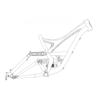
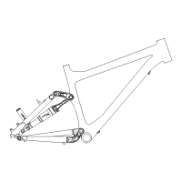
FIG. 2
ROUTE THE WIRES THROUGH THE FRAME
Route a 1400 mm wire through the frame ICR channel exiting at the bottom bracket hole on the drive side.
Route a 700 mm wire starting from the chainstay port and out the bottom bracket hole on the drive side.
Place a rear shift cable grommet over the wire and push it into the ICR port (S1599000054).
There are two ways to mount the dropper post. When running a standard seatpost on a bicycle equipped with Shimano Di2, the battery can be installed inside the seatpost using a Di2 battery
sleeve (S209900014) or attached to the bulkhead.
FOR SEATPOST INSTALLATION (A)
• Route a 1000 mm wire down from the top of the frame post and out the bottom bracket hole on the drive side.
• Install the battery and sleeve in the seatpost. Using the Di2 connector tool, insert the wire into the battery connector, and install the seatpost as described in section 7 of this manual.
FOR BULKHEAD INSTALLATION (B)
• With the bulkhead removed from the frame, slide the battery plug through the bulkhead hole, then zip-tie the battery to the bulkhead. Plug a 300 mm wire into the battery, then install the
bulkhead in the down tube (section 5.9) with the wire exiting out the bottom bracket hole on the drive side.
Plug the three wires into a Junction B box, then insert the Junction B box and the wires into the down tube above the bottom bracket shell.
CAUTION: SWAT bags may not fit properly in the down tube when using a dropper post and could damage the frame if they’re forced into place.