3
E-DOC-CTC-20050705-0001 v1.0
Chapter 1
Getting to know your SpeedTouch™
1 Getting to know your SpeedTouch™
Where’s the power
supply?
Your SpeedTouch™ does not have a separate power supply, simply because it does
not need one. Your SpeedTouch™ is powered through the USB port of your
computer.
Indicator light(s) Your SpeedTouch™ can be equipped with one or two indicator lights. They reflect the
status of the SpeedTouch™ and may be labelled USB and/or ADSL.
At startup, your SpeedTouch™ will go through several phases, also indicated by the
light(s). If your SpeedTouch™ is correctly connected and installed, the light(s) will
turn solid green after startup. This may take up to 12 seconds.
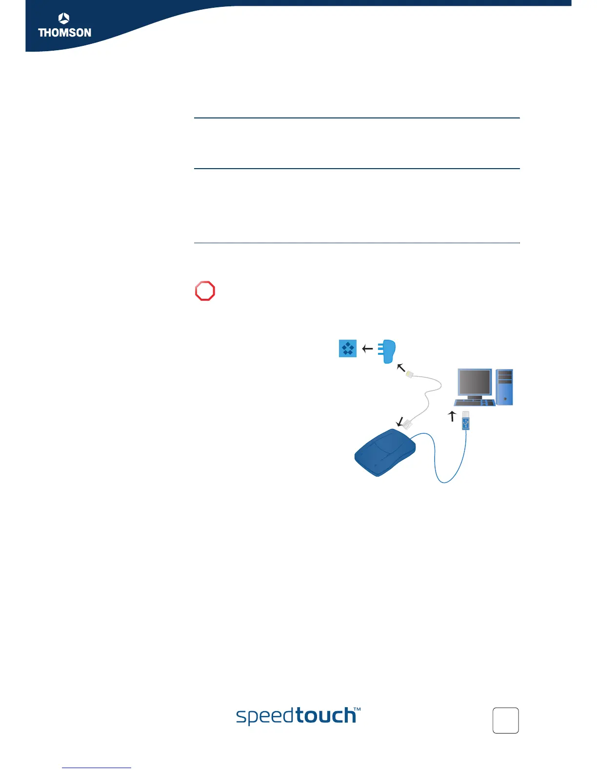
Connection diagram:
typical configuration
The illustration below shows where your SpeedTouch™ fits in in a typical
configuration.
!
Do not connect the cables of your SpeedTouch™ yet. You will be prompted
to do so when you install the SpeedTouch™ software. See “2 Installing your
SpeedTouch™” on page 5.
1 You plug the ADSL
splitter into your
telephone socket.
2 You plug one end of the
DSL cable into the ADSL
splitter and the other end
into your SpeedTouch™.
3 You plug the USB cable
of your SpeedTouch™
into a free USB port of
your computer.
Splitter