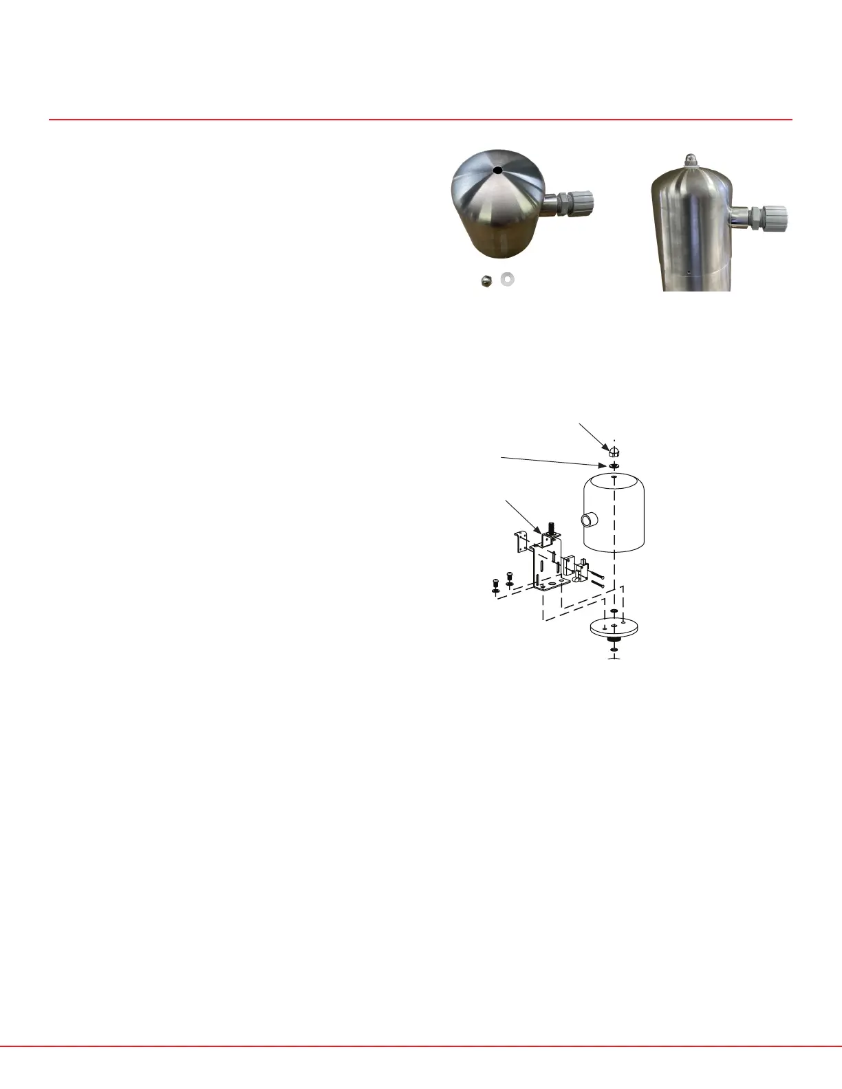
67
6. Wire the microswitches using the labels on
the switch for the terminals (COM1 and NO
or NC). Run the cable through the provided
cable-grip and install the microswitch
housing. The microswitch housing washer
goes onto the stud on the bracket and then
the acorn nut (see fig. 19).
FIG. 17 - MICROSWITCH
HOUSING AND HARDWARE
FIG. 18 - MICROSWITCH
HOUSING INSTALLED
MICROSWITCH ASSEMBLY INSTRUCTIONS
SP10MS/SP10PRX/SP20MS/SP20PRX
FIG. 19 - SP10MS/SP10PRX/SP20MS/SP20PRX ACTUATOR DIAGRAM
MICROSWITCH
HOUSING WASHER
SP10MS-1CW
ACORN NUT
SP10MS-1C
MICROSWITCH
BRACKET
SP10MS-3
 Loading...