61
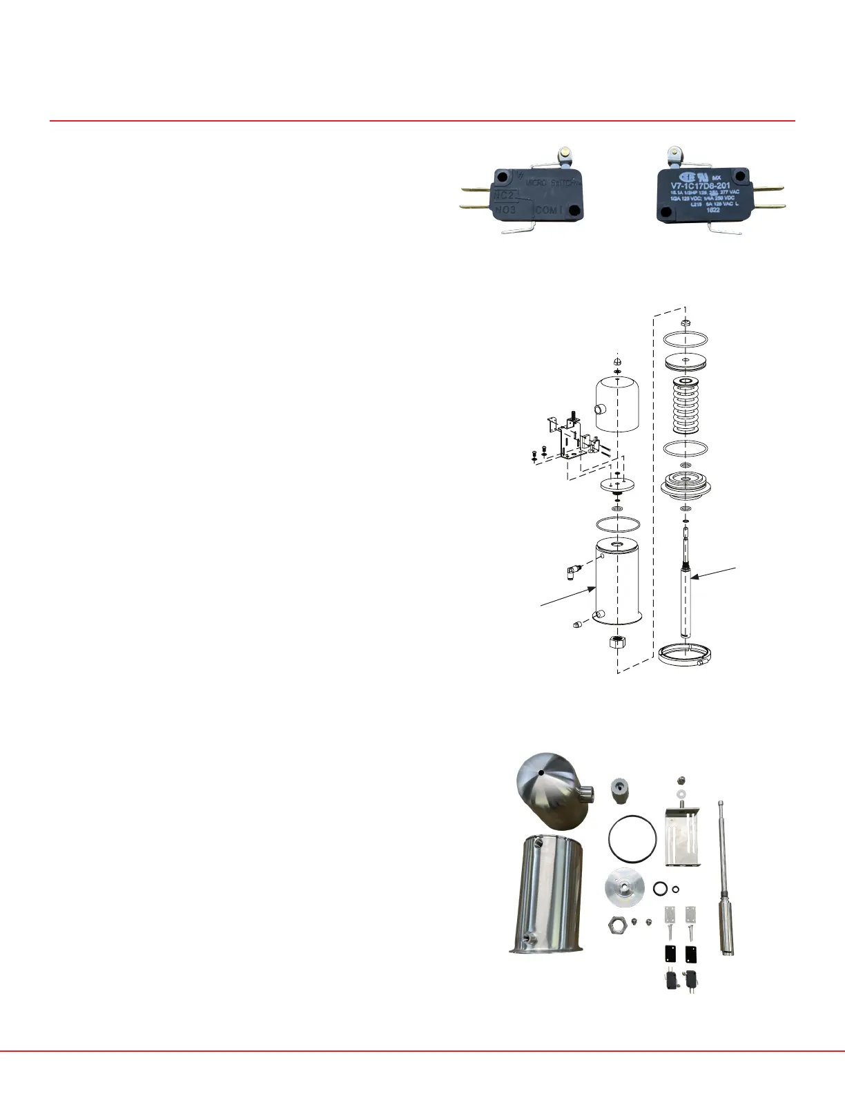
The microswitch top requires some dierent parts
versus the non-microswitch actuator in order to
actuate the feedback microswitches.
• The actuator housing/cylinder (see fig. 2)
has a flat top, with an O-ring groove and
some threaded holes to accommodate the
microswitch bracket and cover
• The actuator stem (see fig. 2) has a special
shaft on top to actuate the microswitches for
feedback. This shaft works through the top of
the cylinder.
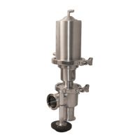
FIG. 1 - MICROSWITCH MODEL AND CIRCUIT INFORMATION
FIG. 3 - MICROSWITCH RELATED PARTS, HARDWARE AND O-RINGS
MICROSWITCH ASSEMBLY INSTRUCTIONS
SP10MS/SP10PRX/SP20MS/SP20PRX
CYLINDER
SP10MS-1
FIG. 2 - SP10MS/SP10PRX/SP20MS/SP20PRX ACTUATOR DIAGRAM
ACTUATOR
STEM
SP10MS-2D
SP20MS-2D
 Loading...