62
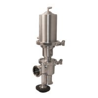
1. Prepare the base plate (see fig. 6) by
installing 1x base plate O-ring and 2x
indicator stem O-ring.
FIG. 4 - O-RING INSTALLATION
ON BASE PLATE
2. Install the base plate (see fig. 6) onto the
cylinder by using the base plate nut. The
baseplate nut is large, and requires a
1-5/16” socket and extension.
FIG. 7 - INSTALLATION OF BASE
PLATE USING THE BASE PLATE NUT
FIG. 5 - O-RING INSTALLATION
ON BASE PLATE
MICROSWITCH ASSEMBLY INSTRUCTIONS
SP10MS/SP10PRX/SP20MS/SP20PRX
BASE PLATE
SP10MS-1B
FIG. 6 - SP10MS/SP10PRX/SP20MS/SP20PRX ACTUATOR DIAGRAM
ACTUATOR
STEM
SP10MS-2D
SP20MS-2D
BASE PLATE
O-RING
SP10-7
INDICATOR
STEM O-RING
SP10MS-40B
CYLINDER
SP10MS-1
BASE PLATE NUT
SP10MS-1BN
 Loading...