87
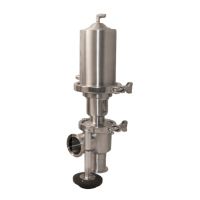
6. Remove the spring and stem nut (see fig. 13)
using a deep-well 9/16” socket. The same
method of holding the actuator stem from
step 5 will need to be utilized.
FIG. 10 - SPRING CLIP AND PLUG
AND STEM REMOVED
FRACTIONAL VALVES ASSEMBLY INSTRUCTIONS
SPRING
SP10-0.5-5
FIG. 11 - FRACTIONAL ACTUATOR
EXPLODED DIAGRAM
STEM NUT
SP10-0.5-12
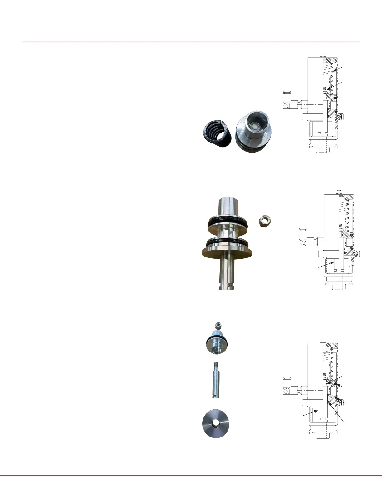
7. Once the nut is removed the actuator stem
(see fig. 15) can be removed to gain access to
and replace:
• Upper stem O-ring
• Lower stem O-ring
• Piston O-ring
• Cylinder foot O-ring
FIG. 12 - STEM NUT REMOVED
FIG. 14 - ACTUATOR FULLY
DISASSEMBLED
FIG. 13 - FRACTIONAL ACTUATOR
EXPLODED DIAGRAM
ACTUATOR STEM
SP10-0.5-2D (N.O.)
SP20-0-5-2D (N.C.)
UPPER STEM
O-RING
SP10-0.5-6
FIG. 15 - FRACTIONAL ACTUATOR
EXPLODED DIAGRAM
PISTON
O-RING
SP10-0.5-8
CYLINDER
FOOT
O-RING
SP10-0.5-9
LOWER STEM
O-RING
SP10-0.5-7
ACTUATOR STEM
SP10-0.5-2D (N.O.)
SP20-0-5-2D (N.C.)
 Loading...