IM-P337- 6 9 EMM Issue 2
18
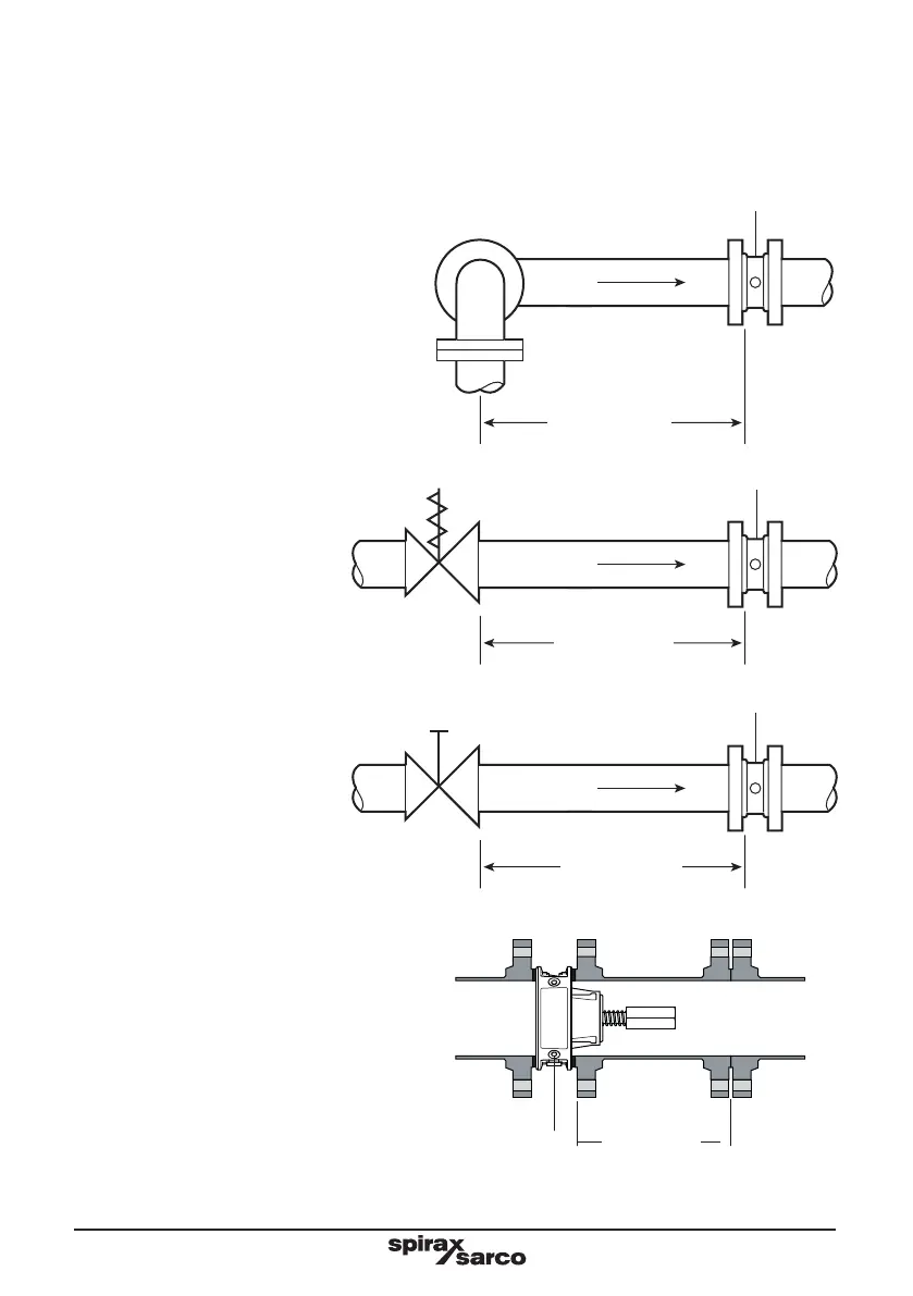
If any of the following configurations are present upstream of the ILVA20, then it is recommended that the
minimum upstream clear pipework is doubled to 12 diameters.
Two right angled bends in two planes.
Pressure reducing valve.
Partly open valve.
Avoid installing the ILVA20 flowmeter
downstream of an actuated valve as rapid
cycling of the valve could give rise to inaccurate
results or damage the flowmeter.
See Figure 12.
Note: D = Pipe inside diameter
Fig. 12
Flow
12 D minimum
Flow
12 D minimum
Flow
12 D minimum
ILVA 20
ILVA 20
ILVA 20
Flow
ILVA20
Fig. 13
Spool piece
We recommend that a spool piece is used to
aid installation and removal (see Figure 13).
See page 11 for dimensions for manufacturing a spool piece.