IM-P337- 6 9 EMM Issue 2
17
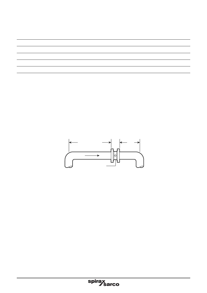
6 D minimum
3 D
minimum
Fig. 11
Flow
D = Pipe inside diameter
ILVA20
4.2 Upstream/downstream pipework
which corresponds to the following pipeline internal diameters.
Nominal diameter Nominal internal diameter
150 mm 154 mm
200 mm 202 mm
250 mm 254 mm
300 mm 303 mm
For different pipe standards/schedules, if the flowmeter is being operated at the extreme of its published
maximum range, downstream spool pieces manufactured from BS 1600 or ASME B16.19M Schedule 40
must be used.
It is important that the internal upstream and downstream diameters of pipe are smooth. Ideally seamless
pipes should be used and there should be no intrusive weld beads on the internal diameter. It is recommended
The ILVA20 normally only requires a minimum of 6 pipe diameters upstream and 3 downstream of clear straight
pipe. These dimensions assume a measurement from a single 90° bend.
See Figure 11.