IM-P402-93 AB Issue 7
12
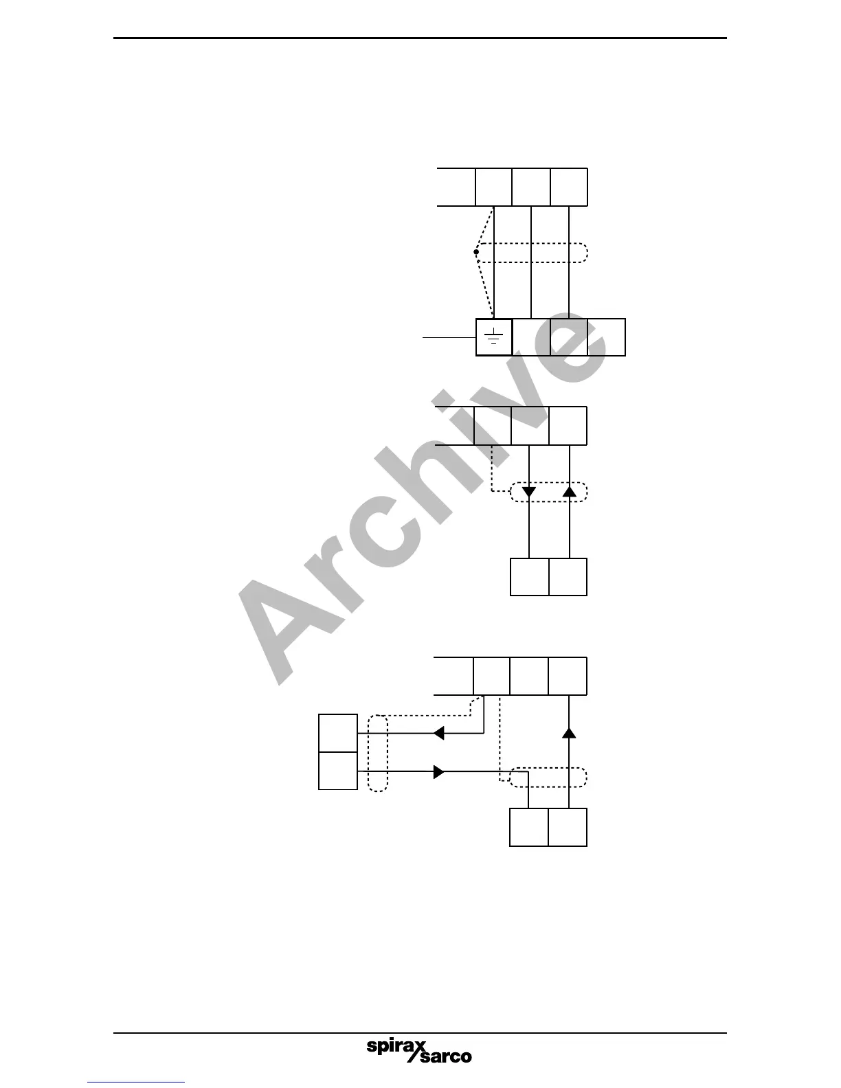
6.4 Level inputs - options (All relays shown in the power off position)
Note: It is essential to select the correct sensitivity on the PA20 preamplifier,
(see the PA20 Installation and Maintenance Instructions for details).
+ Input
1 2 3
7 8 9
Fig. 9
PA20 preamplifier (0 - 6 V) input
(Links on preamplifier provide sensitivity
selection - see the preamplifier IMI for
more information).
+ Input
7 8 9
+ -
External power supply
18 - 30 V (nominal)
+ Input
7 8 9
+ -
-
+
Fig. 11
Externally powered 4 - 20 mA level
transmitter input
The earth terminal is internally connected to
the PA20 body, and earthed by the LP20
probe. Do not connect this earth terminal
to any other earths.
Fig. 10
Loop powered 4 - 20 mA input
(e.g. Two wire differential pressure transmitter)
4 - 20 mA transmitter wiring notes
1. Terminals 7, 5, 3 and 1 are linked inside the controller.
2. Terminal 8 provides loop power of 18 - 30 Vdc.
3. Input resistance between terminals 7 and 9 is 100 W.
LP20 / PA20 wiring notes
1. Terminals 7, 5, 3 and 1 are linked inside the controller and are earthed via the
LP20/PA20.
2. Terminal 8 provides a drive voltage 18-30 Vdc.
3. Input resistance between terminals 7 and 9 is13 k W.
Maximum loop
resistance
750 W
 Loading...