IM-P736-02 EMM Issue 3
39
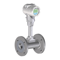
VLM30 In-Line Vortex Flowmeter
Fig. 23 Load diagram of current output; load depending on supply voltage
Devices with HART
®
communication
Terminals PWR/COMM +/PWR/COMM –
Minimal Load R
B
250 Ω
The load R
B
is calculated as a function of the available supply voltage U
S
and the selected signal current
I
B
as follows:
R
B
= U
S
/I
B
R
B
Load resistance
U
S
Supply voltage
I
B
Signalstrom
3.18.4 Current output/HART
®
output
R
B
(kW)
U
S
(V)
1.6
1.4
1.2
1.0
0.8
0.6
0.4
0.2
0
10 12 15 20 25 30 35 40 42

 Loading...