Maintenance Waukesha Cherry-Burrell Brand W60/W80 Valves
Page 44 95-03022 08/2018
O-ring and Bearing Replacement:
4”, 5”, and 6" Adjustable-Spring Actuator
Adjustable-Spring actuators cannot be
disassembled. Do not attempt to cut the
actuator or otherwise disassemble it, as
the compressed spring will present a
projectile hazard.
Adjustable-spring actuators are fully welded and cannot be disas-
sembled or reversed. Only compressed air side seals and bear-
ings require maintenance.
Air-to-Raise, Adjustable-Spring Actuator
1. Remove the valve from the body.
2. Shut off the air and disconnect the air supply line to the
actuator.
3. Disconnect/lockout the electrical power to the valve.
For Adjustable-Spring actuators, unload the spring adjustment
completely before attempting to service the actuator.
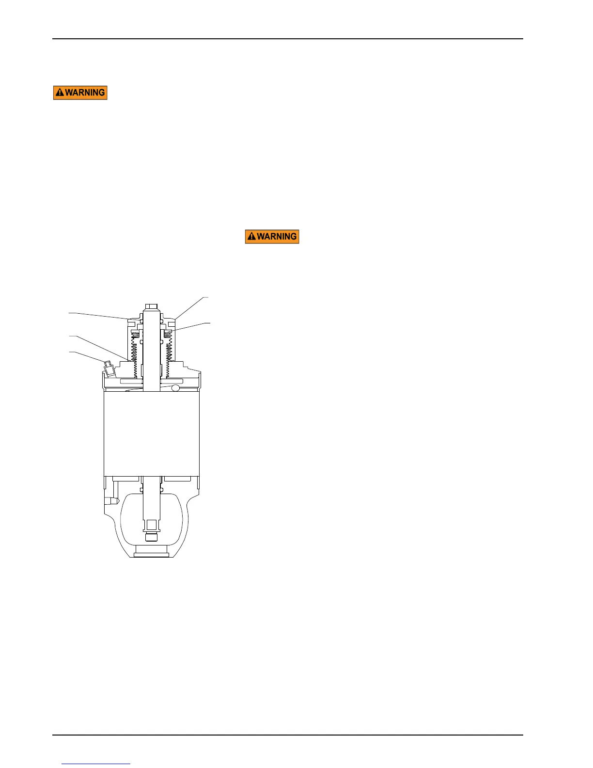
4. Unscrew and remove the locknut cover (Figure 41, item 17).
Unscrew and remove the adjustment screw (item 20). Check
for free movement of the stem to ensure that no compression
remains.
5. nspect the o-ring (item 6) in the adjustment screw (item 20).
Remove the worn o-ring seals. Coat the new o-ring seals with
Dow Corning
®
#7 Silicone Lubricant or equivalent, and
replace them.
6. Remove the PTFE guide bearing (item 5) in the adjustment
screw by placing a screwdriver behind the bearing to pry it
away from the wall of the yoke (item 12). Use needle-nose
pliers to grip and remove the bearing.
7. Using wrenches on the upper and lower wrench flats,
unscrew and remove the lower stem (item 3). Do not remove
the upper stem (item 1), as it locates an internal support
washer.
8. Remove and inspect the yoke area stem o-ring (item 11).
Remove the worn o-ring seal. Coat the new o-ring seals with
Dow Corning
®
#7 Silicone Lubricant or equivalent, and
replace them.
9. Inspect and replace the PTFE guide bearing (item 15) in the
yoke as needed.
10. Reassemble the actuator in reverse order.
11. Once secure, screw in the adjustment screw (item 20) until it
is held by threads (not in its final position). Refer to
Adjustable-Spring Actuators: Pressure Setting (Table 2 on
page 17) for setting it to the desired loading pressure.
Figure 41: 4", 5", and 6" Air-to-Raise,
Adjustable-Spring Actuator
NOTE: On the 6" design, the location of
items 11 and 15 is reversed (see inset).
VA100-660
6
18
13
20