Waukesha Cherry-Burrell Brand W60/W80 Valves Maintenance
08/2018 95-03022 Page 47
Reversing the Spring
Action on the Maintainable
Actuator
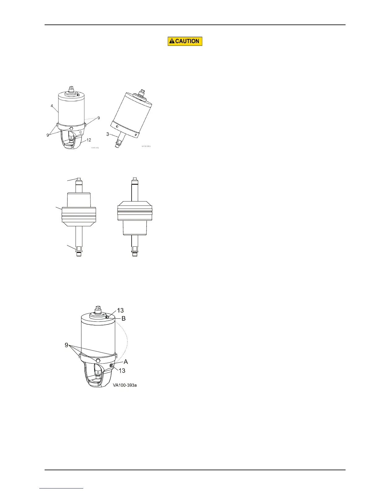
1. Remove the cap screws (Figure 44, item 9) and pull the yoke
(item 12) from the actuator cylinder (item 4).
2. Pull the lower stem (Figure 45, item 3) to remove the caged
spring assembly from the actuator cylinder.
3. Using a 5/8-inch wrench on the lower stem (Figure 46, item
3) and a 3/8-inch wrench on the upper stem (item 2), unscrew
and remove the two actuator stem halves.
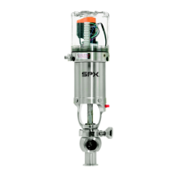
4. Turn the piston/spring assembly (item 10) over.
5. Install the actuator stem halves in the piston/spring assembly.
See Figure 46 for Air-to-Raise configuration; Figure 47 for
Air-to-Lower configuration.
Clean, prime and apply Loctite
®
2440 Thread Locker, accord-
ing to manufacturer’s specifications, to the upper (items 1,
1a) and lower (item 3) stems (See Figure 36 and Figure 37
on page 40). Torque the stems to 200 in/lbs for 4" and 5"
actuators; 400 in/lbs for 6" actuators.
6. Coat the U-cup and o-ring seals with Dow Corning
®
#7
Silicone Lubricant or equivalent.
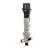
7. Install the piston/spring assembly in the actuator cylinder and
assemble them with cap screws (Figure 48, item 9).
8. Reverse the vent plug (Figure 48, item 13) as follows:
Air-to-Raise Actuator: The vent plug must be located on TOP
of the actuator in Port B (Figure 48, item B).
Air-to-Lower Actuator: The vent plug must be located on the
SIDE of the yoke in Port A (Figure 48, item A).
Although WCB fully-maintainable actuators are designed with a
contained spring for safety, always use caution when handling
any piston/spring assembly as any compressed coil spring can
be extremely dangerous.
Figure 44:
Remove Yoke
Figure 45: Pull
Lower Stem
Air-to-Raise Air-to-Lower
Figure 46:
Remove Actuator
Stem Halves
Figure 47:
Actuator Piston/
Spring
Configuration
Figure 48: Cap Screws and Vent Plug
3
10