SR715/720 LCR METER
xi
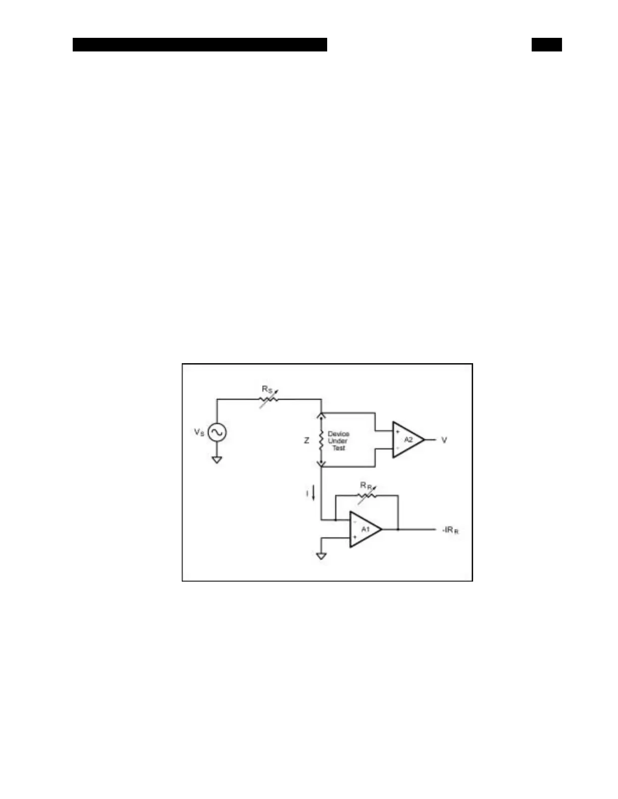
How the SR715/720 Works
The SR715/720 measures the impedance of a
component by measuring the voltage across the
part and the current through it. This is done for
both the real and imaginary (90° phase shifted)
components of the signals. The complex ratio of
voltage to current is equal to the complex
impedance. The processor calculates the various
parameters that are displayed, R, C, L, Q or D.
The voltage across the part is generated by Vs.
Both the amplitude and frequency of Vs can be
set. This voltage is applied to the device under test
(DUT) through source resistance Rs, which varies
according to the measurement range. The current
flows to the virtual ground of A1, and through Rr,
the current conversion resistor. The output of A1
provides a signal proportional to the current, I x Rr.
The voltage across the DUT is measured with a
separate signal path providing a 4-wire Kelvin
connection.
The real and imaginary signals are obtained by
multiplying the voltage and current signals with a
reference signal in phase with Vs and one shifted
90 degrees from Vs. These signals are measured
by an integrating A/D converter which is read by
the microprocessor. These values are corrected by
calibration factors, converted to impedances and
finally converted to the appropriate parameters for
display by the processor.
 Loading...