ACCURACY
3-4
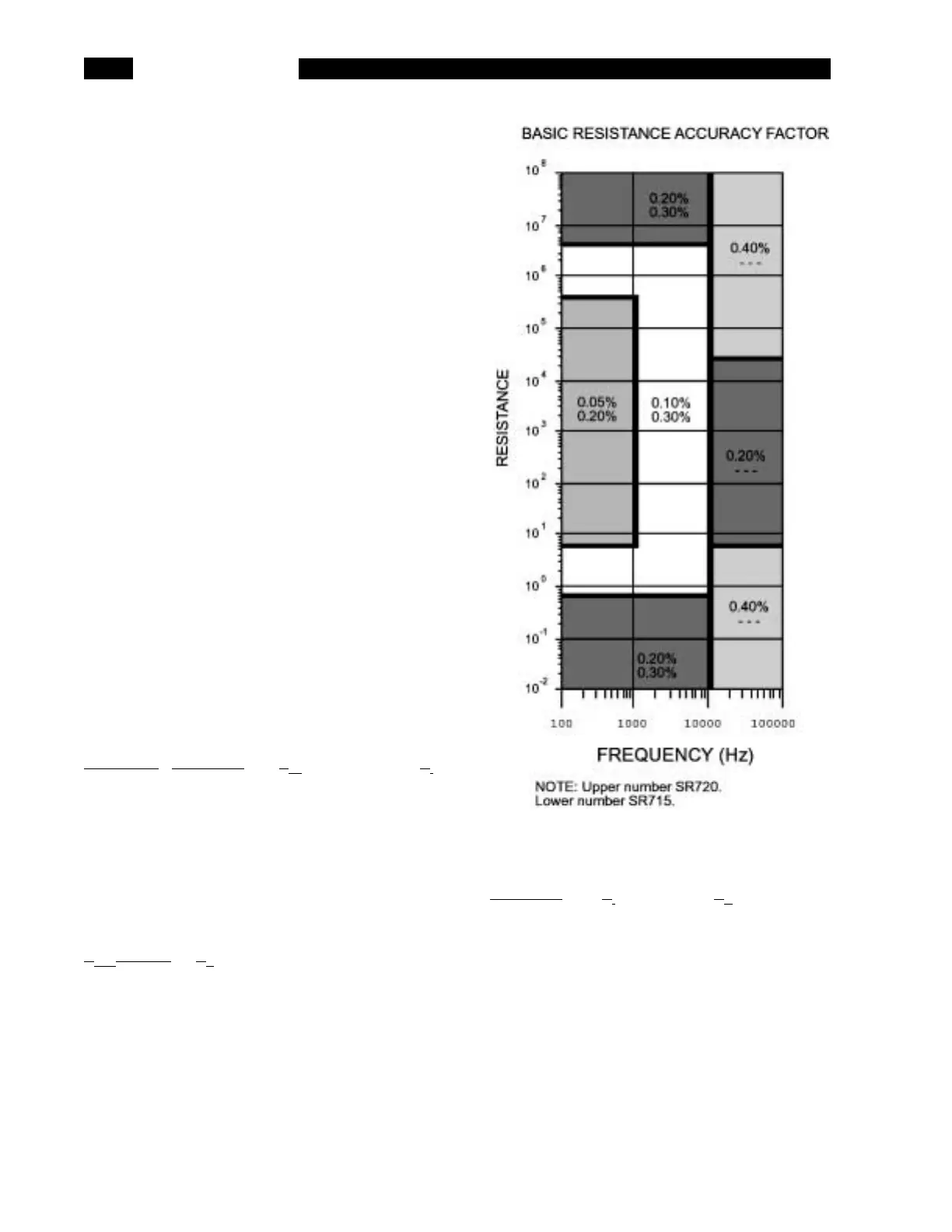
R + Q ACCURACY
Accuracy of R = ± [A x K
i
x K
v
+ (K
h
+ K
l
) x 100] %
A = Basic Resistance Accuracy Factor
from graph.
For |Q| > 0.1, multiply the basic
accuracy factor by (1 + |Q|).
If the unit is in the constant voltage
(CV) mode, double the basic
accuracy factor.
K
i
= Integration Time Factor (see Ki
Table below)
K
v
= Voltage Error Factor (see Kv table
below).
K
h
, K
l
= Extreme Range Error Term (see
K
h
, K
l
table below).
Accuracy of Q = ± [(A
r
/ 100) x (1 + Q2)]
A
r
= the accuracy of the Resistance
measurement (above)
Note that the accuracy of Q is specified as a
magnitude, NOT as a percent.
K
i
Table
Meas Rate Frequency
Z
m
K
i
slow, med all 1
fast 100 Hz-1 kHz 6.25 Ω<Z
m
<400 kΩ 3
fast all other 2
Z
m
= the impedance (resistance) of the device
being measured.
K
v
Table
V
out
(V rms) K
v
1.0 - 055 1 / V
out
0.5 - 0.3 0.5 / V
out
0.25 - 0.15 0.25 / V
out
0.10 0.11/V
out
Note that K
v
equals one for the primary drive
voltages (1.0, 0.5 and 0.25 Vrms).
K
h
& K
l
Table
Frequency K
l
K
h
100,120,1k Hz (1 mΩ / R
m
)(R
m
/ 2 GΩ)
10 kHz (1 mΩ / R
m
)(R
m
/ 1.5 GΩ)
100 kHz (4 mΩ / R
m
)(R
m
/ 50 MΩ)
R
m
= the resistance of the device being
measured.
Note that K
l
is negligible for resistances above
100 Ω and K
h
is negligible for resistances below
1 kΩ at all frequencies.
 Loading...