OPERATION
2-22
Option 01: GPIB/Handler Interface
GPIB Interface:
Detailed information on the GPIB interface and programming examples are available in the remote
programming section.
Handler Interface:
Introduction
The handler interface for the SR720/715 allows the unit to be operated with external hardware to measure and
physically sort components. Data lines for ten sorting bins are provided, as well as control lines (-START, -
BUSY, -BDA) to coordinate measurements. For more information on bin setup procedures and options, refer
to the binning section.
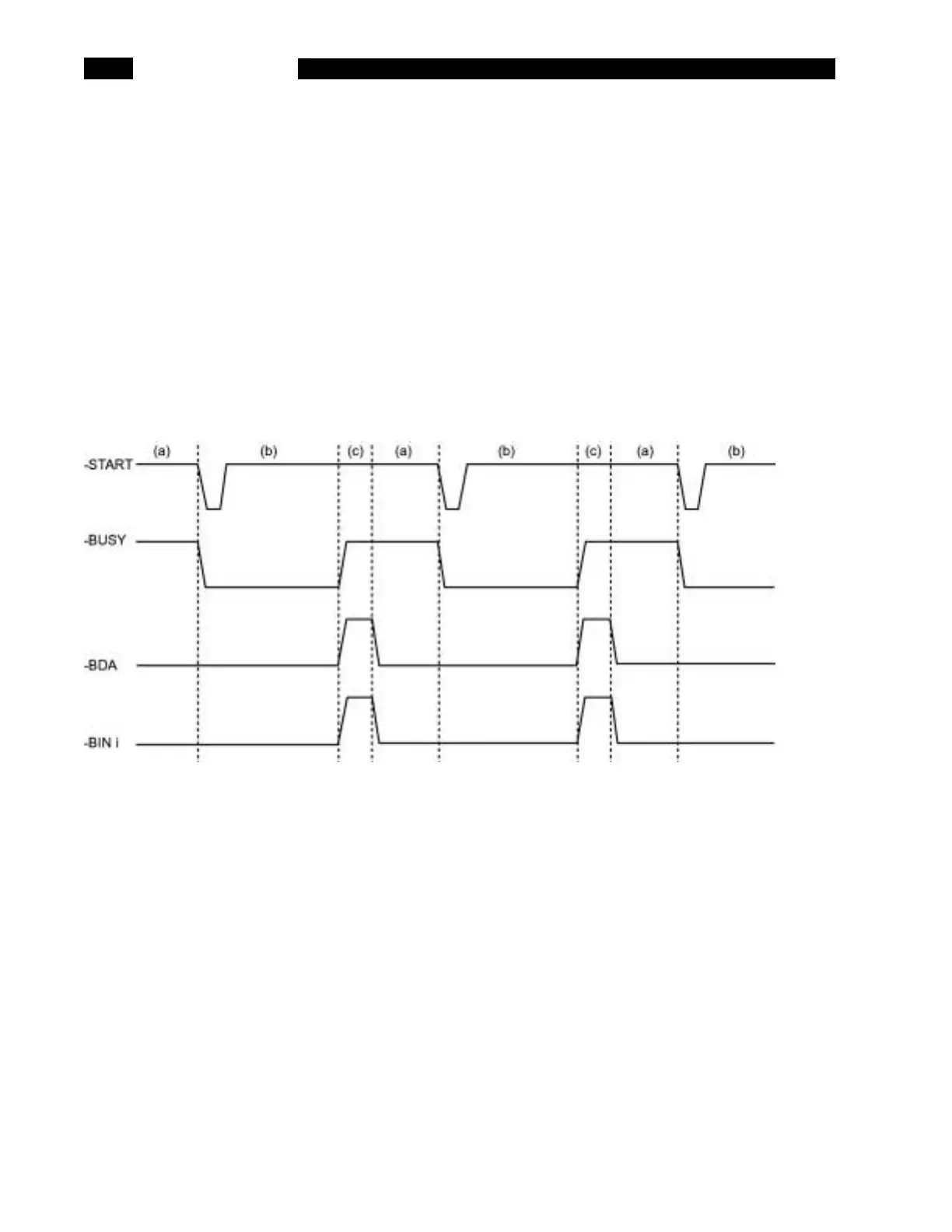
Timing Diagram:
(a) The SR720/715 is waiting for a trigger to start measuring. Previous bin data (if any) is still available.
(b) A negative-going pulse on the -START line will trigger a reading. The -BUSY line will go low and stay
low until the measurement is completed.
(c) After measuring, the SR720/715 determines the proper bin to place the component. During this time
the -BDA (Bin Data Available) line is activated to prevent reading invalid data.
After the proper bin location has been selected, the -BDA line will go high, and the appropriate bin line
will be pulled low (only a single bin line will be low at any one time). The external handler can now remove the
component, place it in the specified location, and insert a new one into the fixture. The SR720/715 is now
again in state (a).
Note: some handlers can be instructed to remove the component under test to the sorting area as soon as the
-BUSY line goes high.
 Loading...