OPERATION
2-15
marked. The side with the silkscreen is the positive side.) To make a
measurement, pick up the component with the SMD tweezers so that the
metallized ends of the parts contact the tips of the tweezers. The tips can be
replaced if they wear out or break. See the maintenance section for details on
changing them.
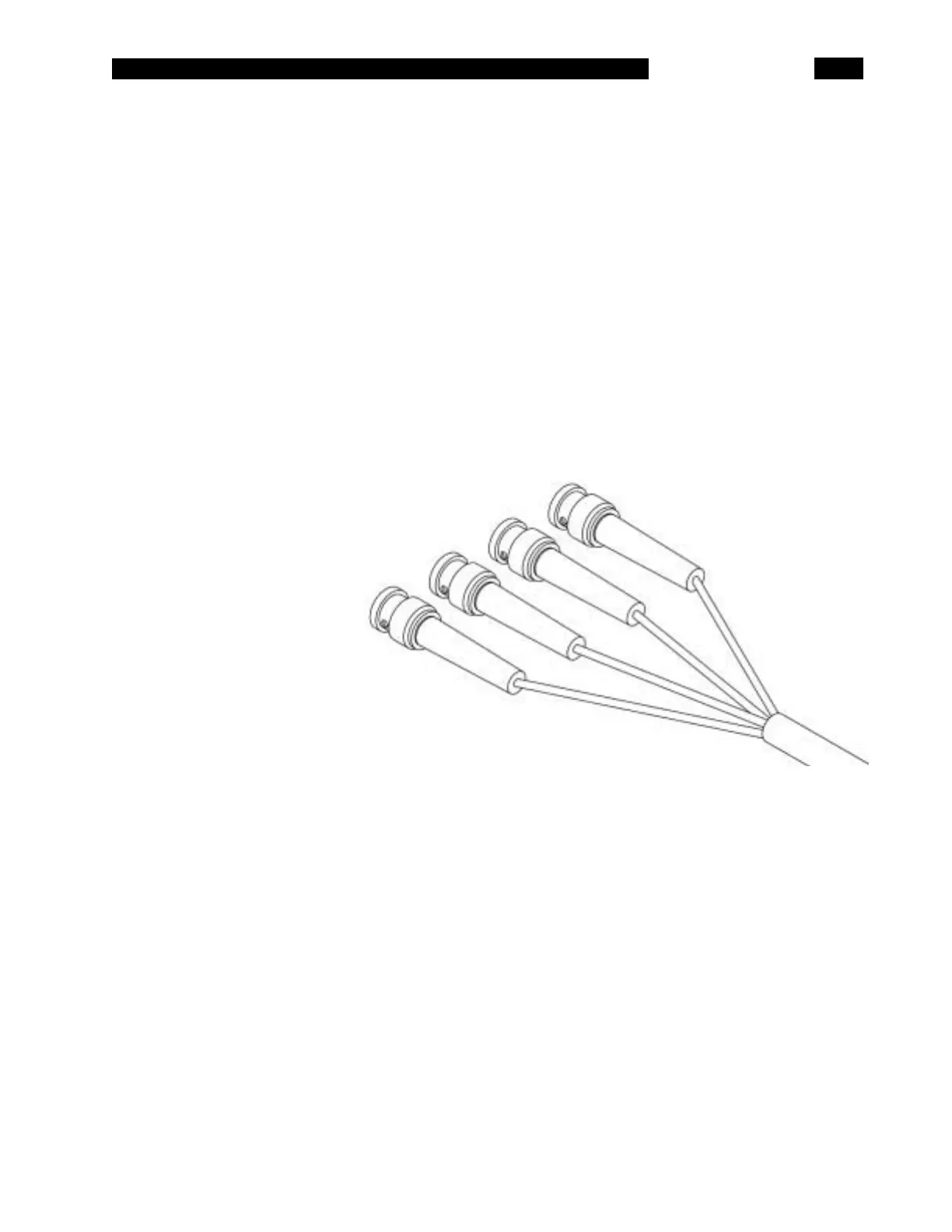
BNC ADAPTER The BNC Adapter Set connects the SR715/720 to other test equipment, switching
networks, or remote test fixtures. The adapter connects to the test fixture in the
same fashion as the Kelvin Clips and SMD Tweezers. The four coax cables are
labeled: Ih (red), the + drive signal, Il (blue), the - drive signal, Vh (orange), the +
sense connection, and Vl (purple), the - sense connection. When connecting
these cables to a device, connect the two + signals to one side of the device and
the two - signals to the other side. The + leads have the same polarity as the
fixture when using DC bias signals. The shields of the four cables should not
connect to each other. The shields of the two drive connections (Ih and Il) should
be connected to each other and to a shield, case or guard at the fixture or DUT, if
possible. The shields of the sense signals (Vh and Vl) should float. If extension
cables are used, it is important that the connector shields do not make contact
with each other.
 Loading...