MAINTENANCE
6-6
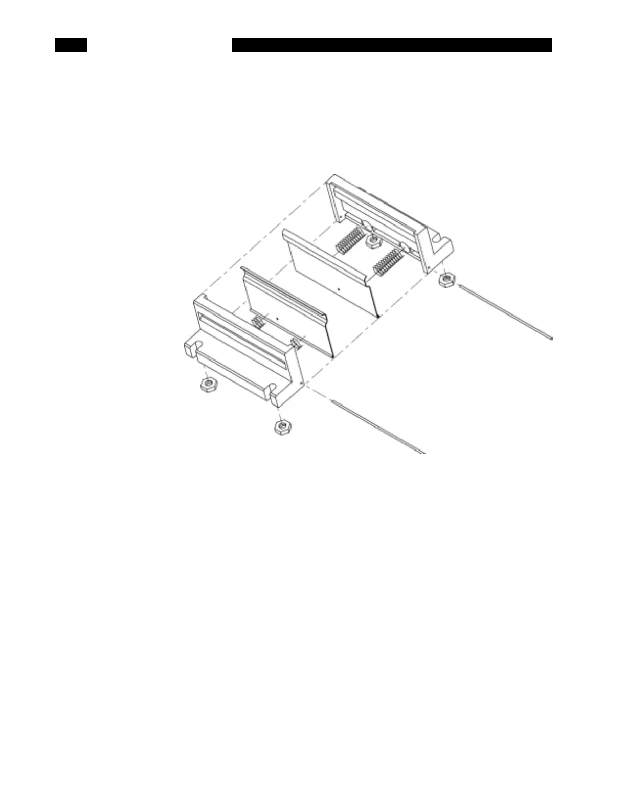
After the fixture bracket is detached, remove the 1/4" nuts holding the fixture to
the bracket. Slide the plastic lead catcher off the mounting studs and wires. The
two halves of the fixture can now be removed. There are springs inside the fixture
so take care to avoid losing any parts when sliding them out of the bracket. Slowly
allow the fixture half to open and remove the springs, placing them somewhere
safe. See the figure below for details on the assembly.
With the fixture halves separated, cut the contact pivot rod at one end and
remove the contact from the plastic housing. Remove the wire from the old
contact. Place the new contact in the plastic housing and slide the new rod to
secure it. Center the contact on the rod and the plastic housing. Solder the rod to
the contact at both ends and in the center. Note: this requires a hot soldering iron
applies for several seconds. Insert one of the wires in the hole at the center of the
contact, near the rod, so that it will come out toward the center of the fixture.
Solder it on the backside of the contact and trim the wire as short as possible.
Repeat this for the remaining three contacts.
To reassemble the fixture, select two housings, each with a different colored lead.
Insert the coil springs in the plastic housings. Press the contacts back into the
plastic housings and carefully bring the two together. Slide them into the
mounting bracket, making sure the black wire is on the left when viewed from
below. Slide the plastic lead catcher over the wires and mounting studs and
replace the nuts. Repeat for the other side.
To install the fixture, attach it to the PCB with the four screws. Insert the wires in
the PCB. See the figure below for the location of each wire. Replace the PCB in
the unit, replace the 12 screws for the PCB, the two screws on the bottom and the
3/16" bolts for the RS232 connector. Replace the option board if present. Attach
the ribbon cable and lugged wire to the top. Replace the top, taking care to align it
 Loading...