DocID028599 Rev 7 15/82
UM1974 Hardware layout and configuration
81
Figure 7. Nucleo-144 board mechanical drawing in mil
6.2 Cuttable PCB
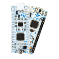
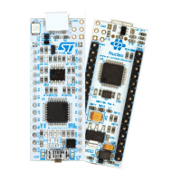
The STM32 Nucleo-144 board is divided into two parts: ST-LINK and target STM32. The
ST-LINK part of the PCB can be cut out to reduce the board size. In this case the remaining
target STM32 part can only be powered by V
IN
, E5V and 3.3 V on ST morpho connector
CN11, or V
IN
and 3.3 V on ST Zio connector CN8. It is still possible to use the ST-LINK part
to program the STM32, using wires between CN6 and SWD available signals on the ST
morpho connector (SWCLK CN11 pin 15, SWDIO CN11 pin 13 and NRST CN11 pin 14).

 Loading...


