DocID028599 Rev 7 27/82
UM1974 Hardware layout and configuration
81
6.10 USB OTG FS or device
The STM32 Nucleo-144 board supports USB OTG or device-full-speed communication via
a USB Micro-AB connector (CN13) and USB power switch (U12) connected to V
BUS
.
Note: The NUCLEO-F303ZE board supports the USB device FS only. All the other STM32
Nucleo-144 boards support the USB OTG.
Warning: USB Micro–AB connector (CN13) cannot power the Nucleo-
144 board. To avoid damaging the STM32, it is mandatory to
power the Nucleo-144 before connecting a USB cable on
CN13. Otherwise there is a risk of current injection on STM32
I/Os.
A green LED LD8 lights in one of these cases:
• Power switch (U12) is ON and STM32 Nucleo-144 board works as a USB host
• V
BUS
is powered by another USB host when the STM32 Nucleo-144 board works as a
USB device.
The red LED LD7 lights if overcurrent occurs when +5 V is enabled on V
BUS
in USB host
mode.
Note: 1. It is recommended to power Nucleo-144 board by an external power supply when using
USB OTG or host function.
2. JP4 must be closed when using USB OTG FS.
The NUCLEO-F303ZE board does not support the OTG function but it supports USB 2.0
full-speed, device-mode communication via a USB Micro-AB connector (CN13). USB
disconnection simulation is implemented by PG6, which controls 1.5
K pull-up resistor (R70)
on USB D+ line. Detection of 5
V power on USB connector (CN13) is available on PG7
thanks to a bridge between R62 and R63 resistors.
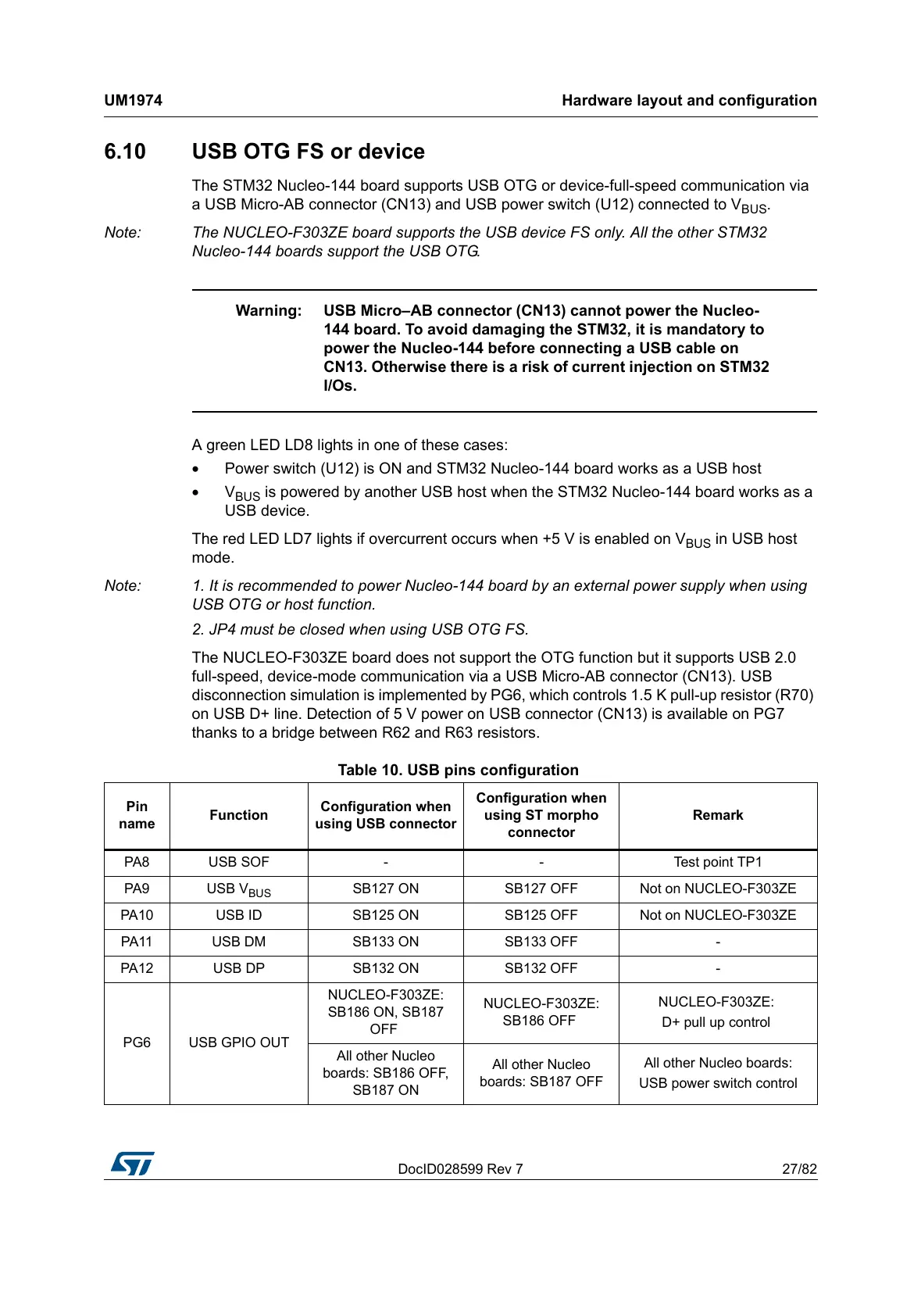
Table 10. USB pins configuration
Pin
name
Function
Configuration when
using USB connector
Configuration when
using ST morpho
connector
Remark
PA8 USB SOF - - Test point TP1
PA9 USB V
BUS
SB127 ON SB127 OFF Not on NUCLEO-F303ZE
PA10 USB ID SB125 ON SB125 OFF Not on NUCLEO-F303ZE
PA11 USB DM SB133 ON SB133 OFF -
PA12 USB DP SB132 ON SB132 OFF -
PG6 USB GPIO OUT
NUCLEO-F303ZE:
SB186 ON, SB187
OFF
NUCLEO-F303ZE:
SB186 OFF
NUCLEO-F303ZE:
D+ pull up control
All other Nucleo
boards: SB186 OFF,
SB187 ON
All other Nucleo
boards: SB187 OFF
All other Nucleo boards:
USB power switch control
 Loading...