UM1075 Rev 10 11/20
UM1075 Hardware configuration
19
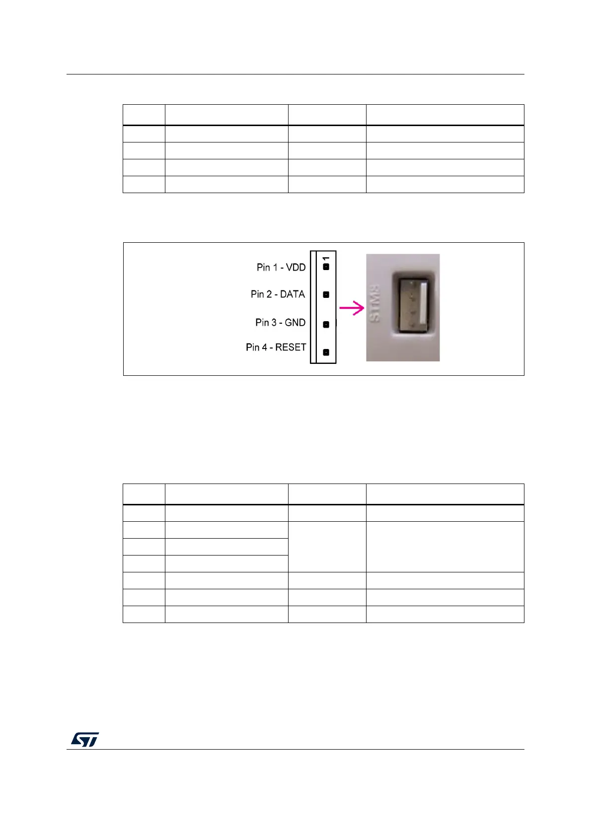
Figure 8. Target SWIM connector
Table 3 summarizes the signal names, functions, and target connection signals using the
separate-wires cable.
As the SWIM separate-wire cable has independent connectors for all pins on one side, it is
possible to connect the ST-LINK/V2-ISOL to an application board without a standard SWIM
connector. On this flat ribbon, a specific color and a label to ease the connection on target
references all the signals.
TVCC, SWIM, GND, and SWIM-RST can be connected to a low-cost 2.54 mm pitch
connector or to pin headers available on the target board.
Table 2. SWIM flat ribbon connections for ST-LINK/V2
Pin no. Name Function Target connection
1 VDD Target VCC
(1)
1. The power supply from the application board is connected to the ST-LINK/V2 debugging and programming
board to ensure signal compatibility between both boards.
MCU VCC
2 DATA SWIM MCU SWIM pin
3 GND GROUND GND
4 RESET RESET MCU RESET pin
Table 3. SWIM low-cost cable connections for ST-LINK/V2-ISOL
Color Cable pin name Function Target connection
Red TVCC Target VCC
(1)
1. The power supply from the application board is connected to the ST-LINK/V2 debugging and programming
board to ensure signal compatibility between both boards.
MCU VCC
Green UART-RX
Unused
Reserved
(2)
(not connected to the target board)
2. BOOT0, UART-TX, and UART-RX are reserved for future developments.
Blue UART-TX
Yell ow BOOT 0
Orange SWIM SWIM MCU SWIM pin
Black GND GROUND GND
White SWIM-RST RESET MCU RESET pin