UM1075 Rev 10 17/20
UM1075 Schematics
19
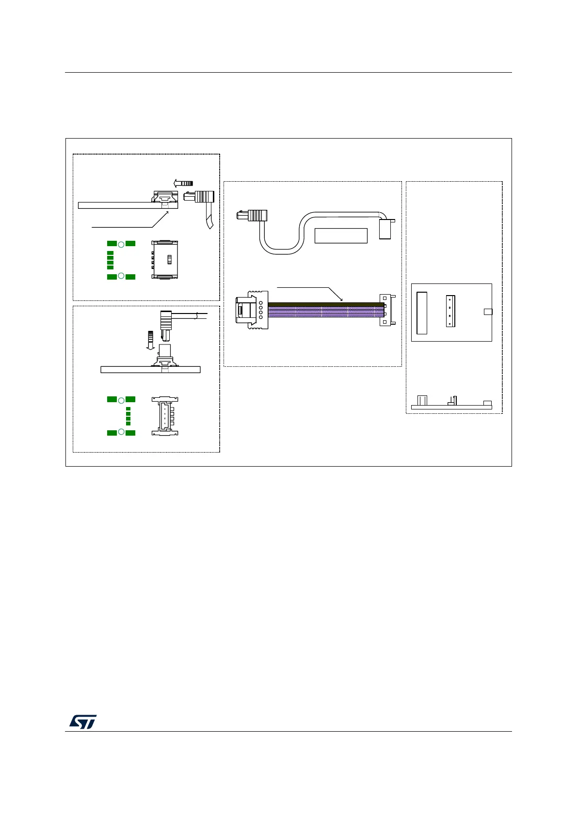
6 Schematics
Figure 11. SWIM ST-LINK/V2 standard ERNI cable
1. Legend for pin descriptions:
VDD = Target voltage sense
DATA = SWIM DATA line between target and debug tool
GND = Ground voltage
RESET = Target system reset
1
ERNI
214012
PCB Footprint
4
3
2
1
PCB Footprint
4
3
2
1
214017
224394
Note: Black wire location
Target board
(horizontal mount)
Target board
(vertical mount)
Note: The connector is located on the
edge of the board
Low cost
female
connector
02 201 3047
Cable length 100mm
STLINK/V2 board
ST-LINK/V2
male
connector 02
20 227 2041
USB
CN3
USB
CN4
1
PCB
ai18745
PIN 1 - VDD
PIN 2 - DATA
PIN 3 - GND
PIN 4 - RESET