Hardware configuration UM1075
12/20 UM1075 Rev 10
4.2 Connection with STM32
For the development of applications based on STM32 microcontrollers, the ST-LINK/V2 must
be connected to the application using the standard 20-pin JTAG flat ribbon provided.
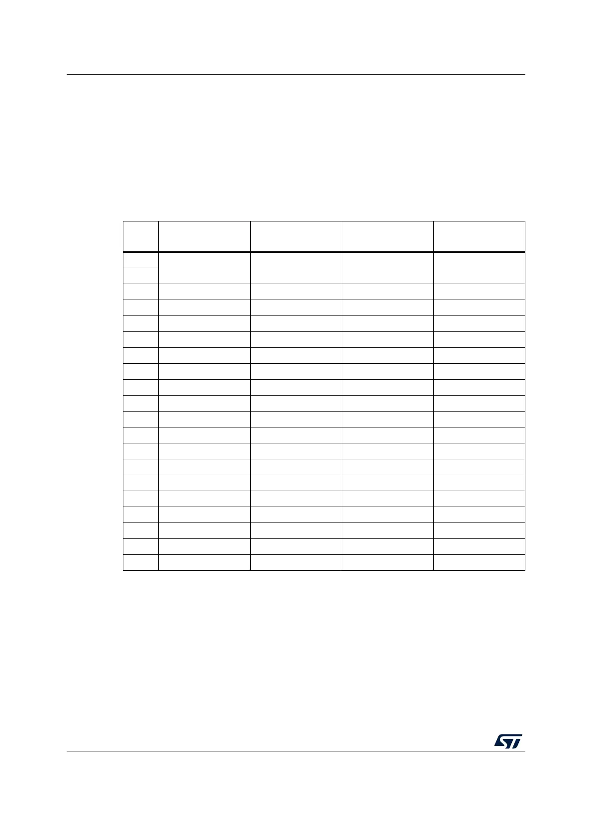
Table 4 summarizes the signal names, functions, and target connection signals of the
standard 20-pin JTAG flat ribbon on ST-LINK/V2.
Table 5 summarizes the signal names, functions, and target connection signals of the
standard 20-pin JTAG flat ribbon on ST-LINK/V2-ISOL.
Table 4. JTAG/SWD cable connections on STLINK-V2
Pin
no.
ST-LINK/V2
connector (CN3)
ST-LINK/V2
function
Target connection
(JTAG)
Target connection
(SWD)
1
VAPP Target VCC MCU VDD
(1)
1. The power supply from the application board is connected to the ST-LINK/V2 debugging and programming
board to ensure signal compatibility between the boards.
MCU VDD
(1)
2
3 TRST JTAG TRST NJTRST GND
(2)
2. Connect to GND for noise reduction on the ribbon.
4 GND GND GND
(3)
3. At least one of these pins must be connected to the ground for correct behavior. It is recommended to
connect all of them.
GND
(3)
5TDI JTAG TDO JTDI GND
(2)
6 GND GND GND
(3)
GND
(3)
7 TMS_SWDIO JTAG TMS, SW IO JTMS SWDIO
8 GND GND GND
(3)
GND
(3)
9 TCK_SWCLK JTAG TCK, SW CLK JTCK SWCLK
10 GND GND GND
(3)
GND
(3)
11 Not connected Not connected Not connected Not connected
12 GND GND GND
(3)
GND
(3)
13 TDO_SWO JTAG TDI, SWO JTDO TRACESWO
(4)
4. Optional: For Serial Wire Viewer (SWV) trace.
14 GND GND GND
(3)
GND
(3)
15 NRST NRST NRST NRST
16 GND GND GND
(3)
GND
(3)
17 Not connected Not connected Not connected Not connected
18 GND GND GND
(3)
GND
(3)
19 VDD VDD (3.3 V) Not connected Not connected
20 GND GND GND
(3)
GND
(3)