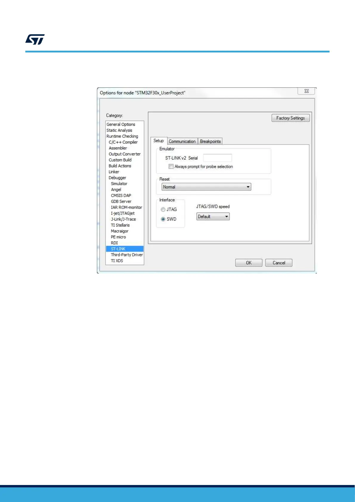
Step 2. Set the SWD interface in the IDE tool.
Figure 11. Sample SWD configuration on IAR tool
Step 3. Solder the three motor wires U,V,W at the motor connector with no particular color sequence.
As shown in
Figure 12. STEVAL-ESC001V1 input/output connection, the right side is for the motor
connection with three pads provided for soldering.
Step 4. Solder the PWM input at J3 connector.
The INPUT pin level must not exceed 3V3.
UM2197
Initializing and using the STEVAL-ESC001V1 ESC board
UM2197 - Rev 3
page 11/25