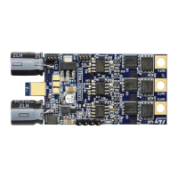
2.1.3 Board dimensions (29.1 x 58 mm)
Figure 8. STEVAL-ESC001V1 board dimensions (not including capacitors)
2.2 Communication, programming and command interfaces
The
STEVAL-ESC001V1 features these communication interfaces:
• CAN port (J1): comes with an on-board transceiver; the J1 connector includes 3V3 and GND pins.
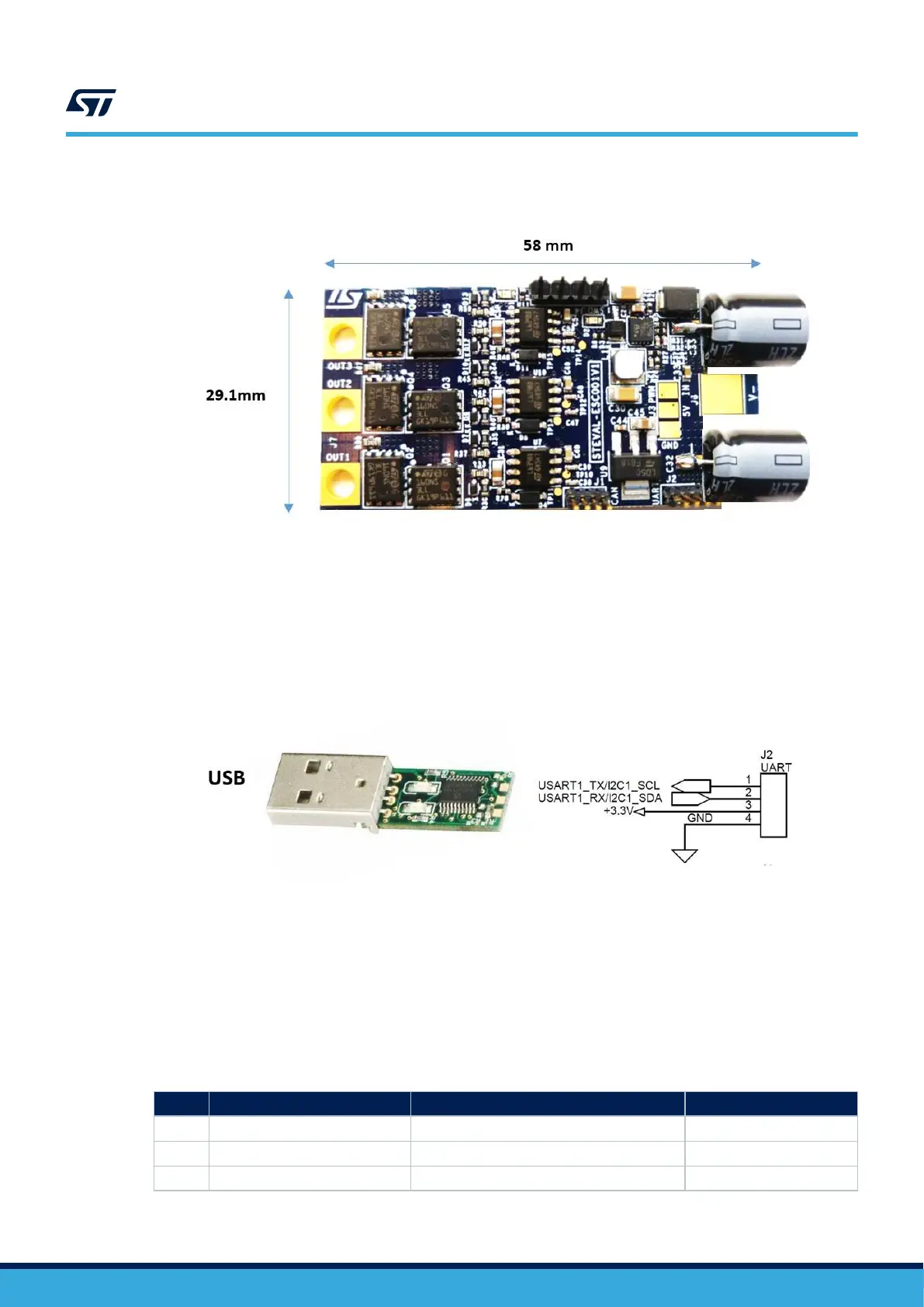
• UART/I²C port (J2): normally used for serial communication between the ESC board and a PC; ST
MC Workbench can be connected with the STM32, adding an external circuit (requires USB/RS232
converter-3v3 level)
Figure 9. UART TX/RX (3v3 level)
• PWM signal input (J3): connects with an external board (e.g., flight control unit), to receive commands; the
signal level (at 3v3) sets the motor speed according to the Ton duration (i.e., 1060 µs for min. speed and
1860 µs for max. speed). Other pins are for GND and a +5Vdc power line to supply an external board
• SWD debug port (J4): provides the SWD connection between the STM32 and ST-LINK programmer; other
pins like 3V3 and GND are available.
2.3 STM32 pinout for motor control
Table 1. Main STM32 pinout for motor control
Pin Default Signal Solder Bridge
1 VBAT 3V3
2 PC13/TAMP/RTC TP4
3 PC14 N.C.
UM2197
Communication, programming and command interfaces
UM2197 - Rev 3
page 7/25