Step 5. Connect the STEVAL-ESC001V1 with a Li-Po battery (or DC power supply: min 3S – max 6S) with the
right polarity and turn ON.
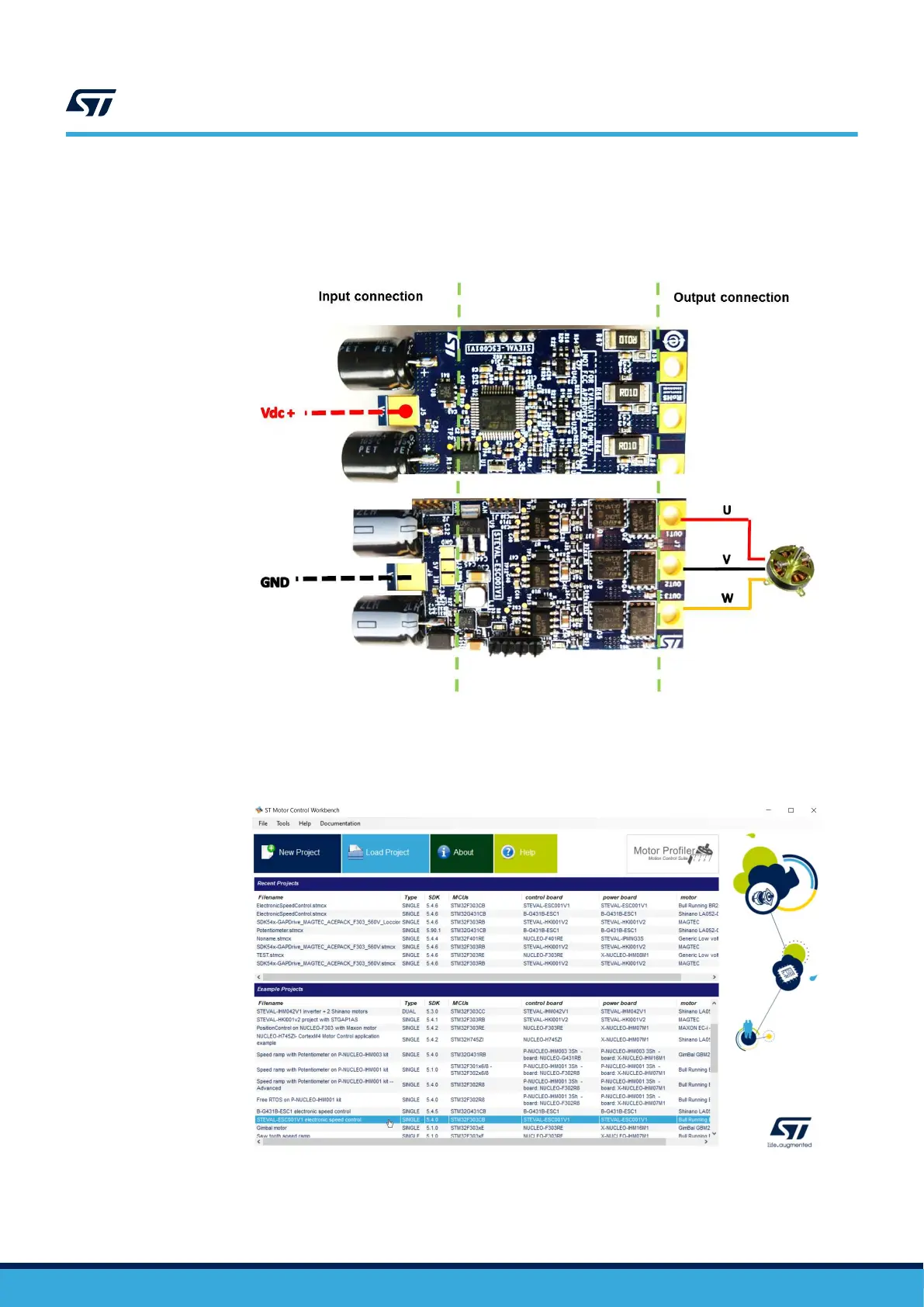
The input connector has two large pads for soldering: the top layer for GND and bottom for Vdc+. A
transil device prevents damage in case of reverse polarity.
Figure 12. STEVAL-ESC001V1 input/output connection
Step 6. Verify if the green led is turned on.
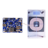
Step 7. Open ST ST Motor Control Workbench.
Figure 13. ST MC Workbench
Step 8. Follow the instructions included in the readme file to compile/upload the example project.
UM2197
Initializing and using the STEVAL-ESC001V1 ESC board
UM2197 - Rev 3
page 12/25