3 Initializing and using the STEVAL-ESC001V1 ESC board
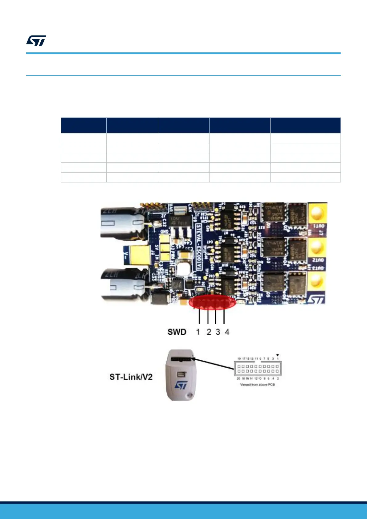
Step 1. Connect the ST-LINK/V2 programmer to the J4 connector on the board.
Table 3. Relationship between the STEVAL board SWD pinout and SWD on ST-Link/V2
programmer
Pin no. in STLINK
ST-LINK/V2
connector
ST-LINK/V2 function
Target connection
(SWD)
Pin no. in STEVAL-
ESC001V1 (J4 connector)
1 VAPP Target VCC MCU VDD 1
2 VAPP Target VCC MCU VDD 1
6 GND 4
7 SW IO SWDIO 3
9 SW CLK SWCLK 2
Figure 10. STEVAL-ESC001V1 connection for MCU programming
UM2197
Initializing and using the STEVAL-ESC001V1 ESC board
UM2197 - Rev 3
page 10/25