EasyManuals Logo

ST STM32 Nucleo-32 User Manual

ST STM32 Nucleo-32
37 pages
To Next Page IconTo Next Page
To Previous Page IconTo Previous Page
Page #11 background imageLoading...
Page #11 background image
UM1956 Rev 5 11/37
UM1956 Hardware layout and configuration
36
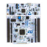
6.1 STM32 Nucleo-32 board layout
Figure 3.
U2
STM32
Microcontroller
CN1
ST-LINK Micro B
USB connector
LD1
(Red/Green LED)
COM
LD2
(
Red LED
)
Power
B1
Reset Button
LD3
(
Green LED
)
CN2
ST-LINK SWD
connector
(reserved)
SB1
Power confi
g
uration
SB2
Connect VCP TX to ST-LINK
SB3
Connect VCP RX to ST-LINK
SB4
Connect PF0/PC14 to MCO
SB6
Connect PF0/PC14 to D8
SB5
Co
nn
ect
PF
0/
P
C
14
to
X1
SB7
Connect PF1/PC15 to X1
SB8
Connect PF1/PC15 to D7
STM32 Nucleo-32 board top layout

Table of Contents

Questions and Answers:

Question and Answer IconNeed help?

Do you have a question about the ST STM32 Nucleo-32 and is the answer not in the manual?

ST STM32 Nucleo-32 Specifications

General IconGeneral
MicrocontrollerSTM32
Pin Count32
ConnectivityUSB
DebuggingST-LINK/V2-1
CoreARM Cortex-M
Operating Voltage3.3V
Power SupplyUSB or External Source
Clock SpeedVaries by specific STM32 MCU
Flash MemoryVaries by specific STM32 MCU
SRAMVaries by specific STM32 MCU
GPIO PinsVaries by specific STM32 MCU
ADCVaries by specific STM32 MCU
DACVaries by specific STM32 MCU
Communication InterfacesI2C, SPI, USART, USB
Expansion ConnectorsArduino Nano connectivity
Operating TemperatureVaries by specific STM32 MCU

Related product manuals